Chebacco News
Number 26, May 1999
GINA – on Kangaroo Island, Australia
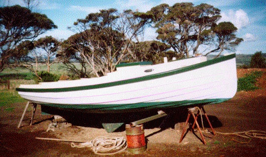
GINA
Colin Hunt, of Victoria, Australia, sent me this picture of GINA – Clive Colenso’s lapstrake Chebacco. He reports a good, dry boat which has been surveyed for charter hire. The waters around Kangaroo Island can get pretty rough. GINA has the cockpit modified to be self-draining with approximately ½ cubic meter of underfloor stowage for outboard, anchor etc.
Colin asks if anyone has the offsets for any version of Chebacco on a computer file in .DXF format? This might lend itself to CNC routing, to allow mass production of Chebaccos!
Chebacco –25 . . .
Simon Jones (also in Australia) reports:
I’m building directly onto the bulkheads which I have moved to new stations , I am intending to rig her with a jib and a small bowsprit to accommodate anchors and larger foresails ( reachers etc, ) the interior has been enlarged to give full sitting headroom and quarter berths as well as a big double forard , taking out the centreboard has allowed me to cut the keel down to a flat keelson reducing draft and giving me a nice companionway to stand in with the hatch open , ( I’m just running thru all the alterations I can think of here ). I have closed in the cockpit at the stern to give me a large lazarette for storage, the cockpit is still 7′ long so plenty of day room … I have jumped up the deck height 6″ all round and instead of a flushdeck style cabin I have changed to the standard box cabin as in the 20 with a 5″ side deck (just enough for one foot, the other using the cabintop) while this is pretty thin its enough to go forard if necessary, however I hope to use
my forard hatch for most foredeck work . I’m keeping the mizzen as I have always found them to be worth every penny.
I’m currently epoxying everything as its obviously easier than doing it after construction, and I hope to have her in the water before the end of the year as I have the luxury of being able to work on her pretty much full time.
Your idea of having a Chebacco meet sound great! … I’d love to fly over to Canada and be in it…. That’s one fantastic cruising ground they have there and a chance to sail there should never be missed (falling in the water however is a one off!…. your firth would be warm by comparison) ok …I wont bash your ear about it all any more … I’ll be sure to get piccies to you when I have them.
Cheers Simon.
Well! This’ll be one interesting boat. As far as I know, it’ll be the very first Chebacco-25 to be launched. Watch this space!
Plywood – your views –
Tim Fatchen – yet another Australian, writes:
[WBS in Chebacco News #25
“So – Write to me about your ideas on plywood. I’ll fess up first – I
used pretty cheap Far-Eastern ply labeled BS1088, though it was
clearly nothing of the kind. It has frog-hair thin outer veneers, and
thickish inner ones. On the other hand the glue is certainly
waterproof and there are few if any voids in the inner veneers. My
theory is that glass/epoxy sheathing would make it acceptable, and
so far I’ve had no problems (3 years after launching). Let’s hear your
stories!”]
Bill, you clearly took the road favoured by the elite. From your
description of the plies, we fairly clearly used the same source for
Flying Tadpole in 1991, except ours was a grade down and didn’t try to
pretend to BS1088 (unless the BS stamp was added later to boost sales).
Nevertheless, still good waterproof glue and very few voids despite the
froghairthin outer plies. After seven years of abuse in Flying Tadpole,
the only problems which have arisen are two or three spots where
checking of the top ply has occurred (a series of slits about 1/2 inch
long, look like razor nicks) and we haven’t bothered doing more than
give them a lick of paint. Longevity was helped by through epoxy
encapsulation.
Our Nymph, even older (1989), was made from the same ply. Even more
abuse, sits for months at a time under the oak tree, gets roughly hurled
onto decks of houseboats occasionally, always makes landfall on sharp
stones lurking in the mud…Various nicks, dings and scratches in the
bottom, brutally neglected, but still absolutely sound (and originally 3
coats of epoxy inside and out, but no fibreglass).
In both cases, the ply was very heavy, though – I suspect mangrove wood
as the inner plies. Only real objection to it is that it’s a dog to work
compared with gaboon – splinters. I’m reminded of this as we’re still
using odd leftovers of 1/2 inch (not as good as the 1/4 inch was for
voids) as backing plates for deck hardware, battery boxes etc.
So that’s seven and ten years respectively of both use and neglect, the
latter being harder on boats…
Tim & Flying Tadpole
A few notes on the Chebacco’s properties
By Giuseppe ‘Pippo’ Bianco
Like most of the CN readers, I’m particularly intrigued by Phil Bolger’s designs and I have purchased plans for the Micro, Long Micro and Chebacco. The latter is very close to what I need: the most boat which conjugates sheet plywood construction, easy transportation, launching and hauling with a trailer, comfort and safety. I’ve not been able to find any data like righting moments and seaworthiness index for the Chebacco, so I decided to try to compute them by myself. After all, I’m a scientist by profession, so, I said to myself, this shouldn’t be too difficult… Well, that is true only in part. A complete analytical description of the interaction between a sailboat, the wind and the sea waves is almost impossible, and probably the only way to get comprehensive and reliable results would be building the boat, stuff her with instrument (like inclinometers, accelerometers, strain meters), sail it in a variety of conditions while recording the data, analyze them and draw the proper conclusions. I’m pretty sure that nobody carries out such measurements except maybe large, well funded designing companies working on super racers involved in world class competitions. So, in the amateur’s world, one is forced to use a mixture of common sense and a few empirical formulas.
A few basic numbers are needed to make a first assessment. Carl Adler (early readers of the Common Sense Design’s Newsletter will recall him as the Micro prototype builder) runs a great interactive sail calculator on the WWW which allows direct comparisons between any pair of sailboats listed in his database, recently integrated by myself with the relevant data for the Micro, the Long Micro and the Chebacco. The URL of his page is http://www.image-ination.com/sailcalc.html.
The parameters one needs to know for each boat are the length at water level (LWL), length out all (LOA), the beam, the displacement and the sail area. For the Chebacco those numbers read as follows (in metrics, yeah):
LOA=5.99 m; LWL=5.04 m; Beam=2.26 m; Displacement=789 kg; Sail area = 16.35m2.
The sail calculator crunches those numbers and rapidly comes out with the following sentences for our boat (compared hereafter with the corresponding data for the Micro and Long Micro):
Category: racer. Carl classifies the boats into four categories: racer, racer/cruiser, cruiser/racer and cruiser, in descending order of performance. Micro classifies as racer/cruiser, while Long Micro gets a cruiser score.
Capsize Ratio: 2.5. This number is an indicator of a boat’s ability to resist to the capsize: a value lesser than 2 is considered good; the higher the number, the more vulnerable is the boat. Micro gets 2.0, Long Micro 1.8, so both are stiffer than the Chebacco.
Hull speed: 5.5 knots . This figure depends only on the LWL. Micro 4.7, Long Micro 5.3.
Sail area displacement ratio: 19.5 . This is an indication of how powerful a sail plan is with respect to the vessel’s displacement. Values around 18 and higher indicate high performance boats. Micro gets 17.5, Long Micro 23.5.
Displacement length ratio: 170 (light). Micro sports a huge 411 (heavy), Long Micro an average 274 (moderate).
Length to beam ratio: 2.24. Micro gets 2.21, Long Micro 2.63. A value of 2.7 is considered average; 2.2 is low.
Motion comfort: 10.6. This numbers depends on a complex way from displacement, length and beam: the higher the number, the more comfortable is the boat. Micro gets 17.8, Long Micro boosts a 20.1.
Be warned that sometimes the ratios above are not plain ratios, but rather complex expressions involving odd powers of the parameters. A good description of the formulas used to compute the above parameters is given in http://home.att.net/~hcyoung/formulas.htm
Well, the empirical formulas above confirm what the Chebacco sailors know already about her being spirited. Her capsize ratio is apparently not so good, such as the motion comfort index which is worse than the Micros’.
Not content yet with these numbers, my next step involved some more in-depth analysis. There are two ways to do that. The first is the old-fashioned one: grab a (modern) scientific calculator and a ruler, make measurements on the plans and compute the sought-for parameters, following algorithms commonly found in books on boat design. The second consists in modeling the boat in a dedicated computer program, which in turn will do all the number crunching. Commercial hull design programs are very expensive and barely worth the expense by an amateur: the free demo versions are, in my opinion, almost useless. Luckily enough, however, there are a few nice complete programs around, available free of charge on the WWW. The ones that I know better are Carene40 and Carene50 by Robert Lainé, Hulls by Gregg Carlson and Hullform 6S by Blue Peter Marine Systems. The Carene family is nice and robust, but it’s a bit lacking when one needs to compute the static properties of a boat. Hulls is great, with the only possible exception being the limited number of sections allowed to model a hull. Hullform 6S is probably the best and most complex, yet relatively easy to use, but unfortunately it doesn’t perform the plate development as the first two. On the other end, it’s not limited to hard chine hulls, and comes with a nice user’s manual.
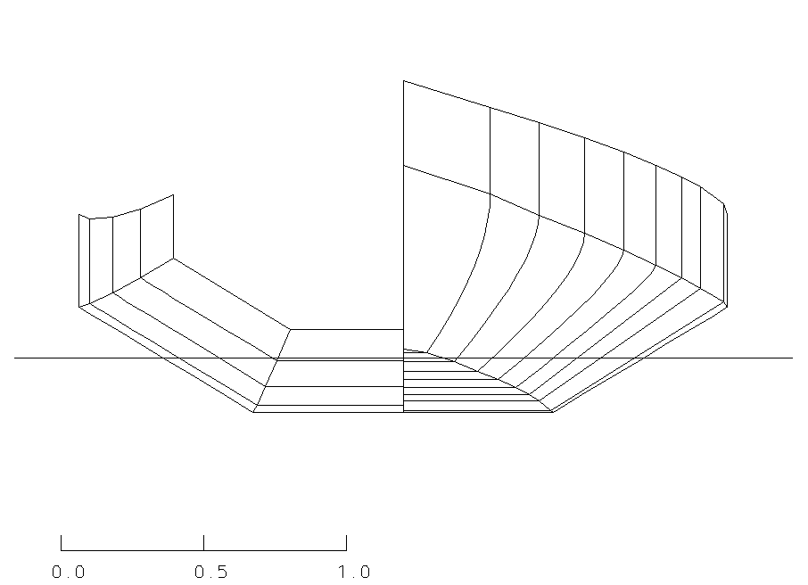
I decided to use Hullform 6S to do my analyses. The first step has been to input all the sections as described in the table of offsets of the Chebacco’s plans. This is quite straightforward. I did that using the 42″ water level as baseline: the end elevation view of the resulting hull is shown in the figure below, where on the right half is the forward view and the left half is the aft view. The scale is in meters. This is very close to the drawings on the original plans, even if admittedly not perfectly fair. I didn’t consider the keel to keep things simple.
Now, in order to perform the static analysis, one has first to balance the hull. I found that my synthetic hull balances very well (i.e. the pitch angle is very small) using the center of buoyancy positions given in the plans, with a few cm tolerance. Using a nominal displacement of 789 kg (1740 lbs.), the plans indicate a bottom draft of 0.193 m, while I find a bottom draft of 0.205 m. This is a difference of 12 mm. Alternatively, to sink the boat at the nominal draft, the displacement would have to be 710 kg (1565 lbs.). I don’t know which one is the correct number. Please note that this is the bottom draft (canoe body draft), not the keel draft.
The nice thing with Hullform is than one can compute the righting moment as well as other parameters for any heel angle. Let me warn you however that my analysis is oversimplified. It doesn’t take into account the combined effect of masts, sails, crew position, wave effects, and so on.
Another warning here: the righting moment computation requires knowledge of the position of the center of mass of a boat, around which the boat rotates when heeling. Longitudinally it has to be in the same position of the center of buoyancy, but the unknown here is its vertical position. This is tough to compute and actually, in the real world, it moves together with the crew and all the stuff on the boat. I first set the center of mass of the Chebacco on the waterline plane, but I’m not sure whether this is true or not. According to Bill Samson, this is a bit too optimistic, so, following his suggestions, I’ve performed the same calculations two more times, respectively lifting the center of mass by 0.1 and 0.2 meters.
Last warning: apparently Hullform treats any hull as if it was completely decked at the sheer level, even if there is no mention of this in the user’s manual. The Chebacco is not decked for a good part, so my results are optimistic.
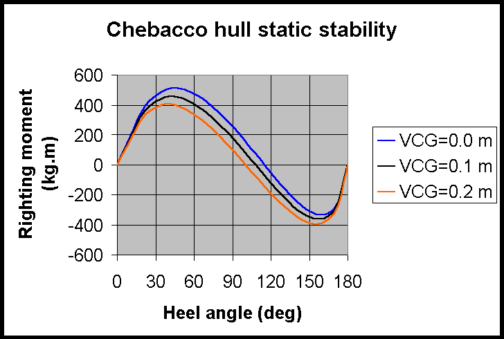
Nevertheless, after 111 runs of the program, here are the plots of the computed righting moments with respect to the heel angle for three different vertical positions of the center of mass, referred to as VCG (vertical center of gravity).
My first (VCG=0.0 m) synthetic hull gets the sheer into the water at about 35 degrees of heel. It is apparently self righting up to about 115 degrees, but over that angle it goes all the way down to settle upside down. Looking at the numbers, there is no chance to right it back by pulling on the centerboard… Note also how the curves move downwards when VCG increases, indicating the well known effect of worsening stability. For VCG=0.1 m, the sheer at midships gets submerged at an heel angle of about 40 degrees, and the righting moment vanishes at about degrees. Finally, for VCG=0.2 m, the sheer gets under water about 45 degrees and the boat is self righting up to about 95 degrees of heel.
An important number used to assess the stability of an hull is the ratio between the area under the curve with positive righting moments to the area over the curve where the moments are negative. In our first case (VCG=0.0 m), this ratio is about 2.7, reasonably good, but it goes down to 1.9 for VCG=0.1 m and to 1.3 for VCG = 0.2 m. After having computed these and several more parameters (actually Hullform does everything), one opens “Principles of yacht design” by L. Larsson and R. E. Eliasson at page 54, enters those numbers in the equations therein and computes a magic number, called the Dynamic Stability Factor (DSF). The Chebacco’s parameters for VCG=0.0 yield DSF=11, placing our beloved boat among the “inshore” vessels. This classification, endorsed by the International Standard Organization, classifies vessels into 4 categories following the water conditions they’re qualified for: sheltered (DSF<10), inshore (10<DSF<25), offshore (25<DSF<40) and ocean (DSF>40). The most penalizing for the Chebacco is the so-called Beam Displacement Factor, which apparently indicates that the beam of the Chebacco is too wide with respect to her typical displacement. However, increasing the displacement is not that effective in getting better figures for the DSF, and this apparently confirms that Phil Bolger and Brad Story are right (surprised?) when they say that additional ballast would be useless in the Chebacco. On the other hand, a slightly narrower beam (e.g. 2.0 m instead of 2.2 m) would have boosted the DSF to much more seaworthy values. The situation obviously worsens for VCG=0.1 (DSF=9), and for VCG=0.2 m (DSF=7). Hence, based on the above criteria, the 20′ sheet ply Chebacco is marginally qualified for inshore waters.
It needs to be said however that this flaming of the wide beamed boats came after the infamous Fastnet disaster in 1979, in particular because those boats are more easily capsized due to the action of big (b-i-g) and breaking waves and, when capsized, are more stable upside down. I don’t think that any Chebacco sailor would ever try to test his boat in really bad seas, so watch the weather forecasts… In any case, like Bill Samson said elsewhere in the CN, this reasoning is academic because there’s no notice yet of a Chebacco having been capsized.
Given the flared sections of the Chebacco’s hull, I tend to think that the computed DSF values are a bit underestimated, and I would conclude by saying that those boats “…are very good in rough water and forgiving in squalls and with prudent and skilled handling and not exceptionally bad luck would get over the North Sea, or the ocean for that matter; but by present day standards they are inshore and fair-weather boats”.
P.S.: for those who didn’t catch it yet, the last sentence is Phil Bolger’s opinion on his Chebaccos. I’m by no means an expert in boat design, and my speculation should only be considered as the result of a few pleasant hours of work of an amateur boat builder during a rainy week-end. Nevertheless, I would love to hear PCB’s opinion on this “paper”…
Bibliography
Lars Larsson and Rolf E. Eliasson 1994. Principles of Yacht Design. Camden, Maine: International Marine
Howard I. Chapelle 1936, 1994. Yacht Designing and Planning. 2nd Edition. New York, London: Norton
Philip C. Bolger 1994. Boats with an Open Mind. Camden, Maine: International Marine
Tabernacle and Bowsprit
David Neder writes
I am located in the city of Waukesha, Wisconsin. About 90 miles NNW of Chicago
or twenty miles due west of Milwaukee/Lake Michigan.
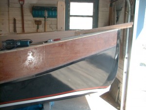
I am attaching photos of the “Anna C”.

Bow with tabernacle and short sprit.
Since the boat will be trailered and I am too long in the tooth to wrestle with a mast, I added the tabernacle. Its section modulus in both the x and y axis is twice that of the mast at the pivot
point.
Materials: 1/2 Fir Marine Plywood, Ribbon strip mahogany plywood, mahogany, red oak, West Epoxy, Fiberglass. Two part poly-urethane paint on the exterior. Interior is paint with Acrylic paint with a fungicide. Construction is taped seam.
David J. Neder
And finally
David sent some other images, too, but there’s no more room in this issue. Neither is there room here for all the plywood-related comments, so they’ll have to be held over as well.
Please send your contributions to me, Bill Samson, 88 Grove Road, Broughty Ferry, Dundee, DD5 1LB, Scotland. wbs@sol.co.uk


