Chebacco News
Number 19, January 1998
Is Electric Outboard Power feasible for a Chebacco?
Gil Fitzhugh wrote to Phil Bolger and Friends –
Dear PCB&F,
. . .
I’ve been intrigued by ‘Lily’ [the electric launch] and saw her or a sister ship at St Michael’s last month. I’m not looking to build or own a power boat, but I’d welcome your views about whether the newest electric outboards with a modest number of batteries would provide reasonable auxiliary power for a Chebacco. I shouldn’t think I’d need to motor more than 3 hours between charges – usually less, since I wouldn’t go anywhere far in a Chebacco if I couldn’t anticipate reasonable sailing – and maybe a couple of solar panels on the cabin roof (or deck house) would replace, during a day’s sail, what I’d used up motoring out of harbor in the morning. Otherwise, I figure a 5-horse Honda 4-stroke would be the next-most environmentally friendly source of adequate power. Thoughts?
Best regards,
Gil Fitzhugh
PCB&F replied –
Dear Gil,
. . .
On your E-power idea, the matter is straightforward and viable for the milder duty cycle you propose if you take it seriously. Before LILY, we hung two smaller 42lbs thrust MINNKOTAs on Ted Ratcliff’s 20′ ply Chebacco ‘KATTEPUS’ and she went quite well, only hampered by the limited pitch (one size only available) on the props.
The following hardware should be good for up to 5 hours of continuously powering your boat:
- 65/70lbs thrust 24 volt MINNKOTA (saltwater series optional for coastal use) [$430],
- 4x6V TROJAN T-105 for 217Ah (or T-145 for added range and cost!) [4x$49 or $129] connected in series to get 24V, but interruptable by
- single battery switch into two banks of 12V [$20], which in turn can then be charged readily in less than overnight by a
- 40Amp STATPOWER 4-stage ‘smart’ charger with two-bank output to feed each 6V T-105 pair with 20Amps as de facto one battery [$350]
- You could add an E-meter [$160] to gauge consumption and get instant reading on voltage and actual amp and amp/hr numbers – useful and instructive.
This will cost more than any combustion engine. But after initial installation, and very minor battery maintenance you’ll be running her for years without additional worry, never mind noise, vibration or oil-plumes – decent return for the money. E-cost will be on the order of perhaps 80c-$1 per total charging cycle . . . But always recharge immediately after you bring her back within reach of the nearest 110V outlet.
Put two batteries in about the location in each cockpit bench where [the Cruising Chebacco] plans show a single one. And locate the expensive charger inside the cuddy/house to keep it out of the rain. LILY’s rain-proof units would take twice as long to recharge these 6V pairs, and seem thus way too wimpy for the occasion. Your E-CHEBACCO would have about 2/3 the capacity of LILY. You probably won’t see more than 4Kt due to the limited pitch on that 11″x4″ prop.
. . .
Susanne Altenburger
Phil Bolger
Hanging the bilge planks on a Sheet Ply Chebacco:
Skip Pahl has been comparing notes with Jamie Orr regarding the hanging of bilge planks. He kindly copied this email to me:
Dear Jamie,
Thanks for all the good information in CN about your building methods and
experiences. Your advice is really timely for after several years of
deliberations, courage and model building, I began cutting wood this summer.
Progress is slow. My building speed is limited by the ability to buy only
three sheets of plywood (or its $ equivalent) every two weeks! Add to this
the fact that I’m very slow when it comes to new types of construction and
you’ll understand why I am straining for new wisecracks to answer the
inevitable question, “So, when’s the big launch date?”
I am writing to you because it is approaching the time to hang the bilge
planks and I am struggling to visualize the process. I too wish to avoid
building all that stress into the hull that 1/2″ ply creates when making that
“Gawdawful” twist and have decided to go with the 1/4″ ply laminations.
I made 7:1 scarf joints when I layed-up the 1/2″ sheer strakes and bottom.
They worked out really well. The curves are fair and the joints appear to be
very strong. However, with laminated bilge strakes it looks as though the
butt block is the way to go. Would you review my thinking here and see if
I’ve got the process right?
PART 1 ( (No volunteers required)
1) Trace mylar or craft paper templates on bilge openings on each side.
2) Transfer template shapes onto for bottom layer plywood. Cut out and
coat outboard surfaces with rolled layer of unthickened epoxy. Allow to cure
and sand.
3) Make 4″(?) wide butt blocks out of 1/4″ plywood and attach to aft end
of each of the forward sections of the bilge strakes. Use thickened epoxy and
bronze screws to clamp.
4) Attach forward section of each strake to the stem using bronze screws
only and begin working aft making temporary clamp blocks that are attached to
the shear strake and bottom. Use wire stitches as needed to fair.
5) Attach aft end blocks to middle sections of bilge strakes.
6) Hang middle sections of bilge strakes by beginning at the forward end
butts and working aft. Use bronze screws and epoxy at the joints with wire
stitches at the top and bottom to keep joints fair. Work aft using wire
stitches and clamp blocks (no glue).
7) Hang aft sections of bilge strakes using bronze screws on transom.
8) Go back and unscrew planks at stem and transom and reattach with
epoxy and epoxy/cabosil putty.
PART 2 (Volunteer required)
1) Transfer template shapes onto top layer of unjoined plywood and cut
out.
2) Pre-drill an 8″ grid of holes in exterior panels to allow for escape
of air pockets in laminating.
3) Masking tape interior seams closed so epoxy will not run into
interior of hull.
4) Dry fit exterior lamination panels and mark for future positioning.
5) Beginning with the center panel, roll thickened epoxy onto outboard
surface of inside lamination and unthickened expoy onto inboard surface of
exterior lamination.
6) Join the two panels with pan headed screws beginning at the center
and working forward and aft.
7) Apply forward and aft sections of exterior lamination in similar way
using bronze screws along the butted seams. No butt blocks are used on these
seams inside the hull.
8) Before epoxy has cured, apply unthickened epoxy to seams and follow
with epoxy/cabosil putty mixture to fair.
Sorry this took so long. Please let me know if I’ve got it screwed up. I
have nightmares of things getting stuck together crooked.
Thanks for your help.
Skip Pahl
These sound like sensible procedures. My only comment is that I’d probably thicken the epoxy, a little, between the laminations – but that’s just personal prejudice.
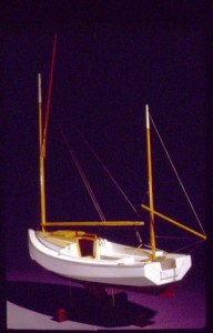
Skip also sent this photo of a gorgeous model he’s built of a sheet ply Chebacco:
Skip Pahl’s model of a Chebacco-20
Uncured epoxy
Just about every boatbuilder will at some time in their career experience the horrors of uncured epoxy. This happened to Burton Blaise, who sent this nessage out to a few of us. In short, getting it off is not a lot of fun:
In case anybody is interested in my continuing epoxy saga, I am
pleased to report that, after a gruelling week-end of scraping, grinding
and sanding, I finally got all of the gummy epoxy off my Chebacco hull
and am back at where I was a couple of weeks ago (that is, ready to
complete glassing the hull – weather permitting!). As mentioned in an
earlier message, I found that the straight edge of a piece of broken glass
really works best to scrape the majority of the goo off. Any remaining
residue was removed using a belt sander fitted with a very coarse
sanding paper (30 or 40 grit). Anyone attempting the broken glass trick
should bear in mind the need to be EXTREMELY careful during the
scraping operation – I got carried away and careless, with the result that
my glass scraper broke in mid-stride, causing my hand to slip past the
glass edge and slicing a good way into my right index finger (after
bandaging my finger – which probably really should have gotten stitches
– I wisely resorted to completing the operation wearing thick canvas
gloves). This hull hasn’t even been launched yet, and already its been
baptized with my sweat, my tears (of frustration) and now my blood!
However, the way things are shaping up, I know that she’ll be worth it all
in the end. Yep, she sure is a shapely hull.
Burton
I’m certainly glad to hear it worked out OK eventually!
Chebacco too big for you? – Try a ‘Bobcat’!
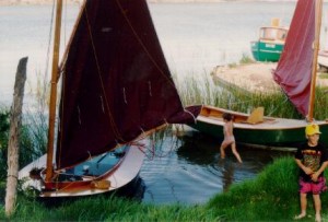
Colin Hunt of Australia sent me this photo of a pair of Bolger ‘Bobcats’ (a.k.a. ‘The Instant Catboat’, ‘Tiny Cat’, ‘Little Gaffer’ . . .). Colin points out that the construction of the 12 foot hull is very like that of a sheet-ply Chebacco hull. They are excellent daysailers and family dinghies, too. So – if you’ve not quite decided that you’re ready to take on the construction of a Chebacco-20, why not hone your skills by building a ‘Bobcat’? Plans are available through PCB&F, as well as Dynamite Payson, who has also published the excellent ‘Build the Instant Catboat’, which is an almost indispensible aid to construction.
A pair of ‘Bobcats’ by Colin Hunt.
Reefing systems for a Chebacco
I was recently caught out in a force 5, under way, single handed, and had the uncomfortable job of trying to put a couple of reefs in while slithering around on the cabin top, avoiding being swept overboard by the flailing boom. It’s no secret that the Chebacco is fairly tippy, initially, (though with superb secondary stability) and so whatever side you approach from, the boat heels in that direction and the swinging boom heads your way! I eventually backed the mizzen a little so that she hove-to on port tack and thus was able to approach the boom from the starboard side, where the cleats for the reefing pendants are attached.
Although I got her well enough reefed to sail the 7 miles back to my mooring, the sail was a tad baggier than I thought ideal, and I felt there must be an easier way to do things. So I phoned Brad Story, who has built and sailed more Chebaccos than anyone else. He suggested that I would have been better to lower the boom into the cockpit, or into a boom crutch to hold it steady while I was working on the reefing. Seems obvious now; I wish I’d thought of it! Secondly, the cleats for the reefing pendants should be positioned so that they can be reached from the cockpit. Good thinking!
Brad writes:
Dear Bill,
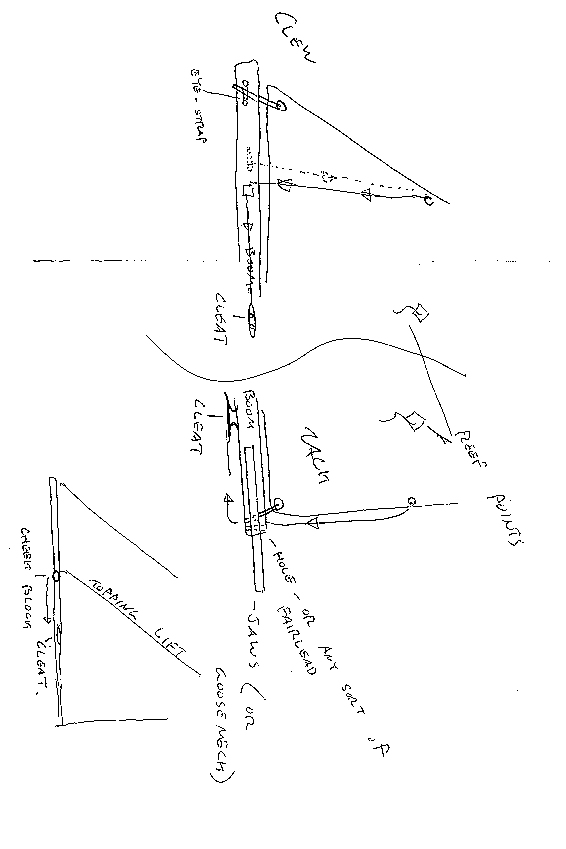
I’ve tried to sketch some details of my own rig. The topping lift is on one side only (keeps it simple!). At the mast head is a loop spliced into the topping lift. It’s held up there with an eye-strap or two. From there it just runs to a cheek block on the boom, and then forward to s small cleat. It’s very handy – it’s right in the cockpit. It can never fall down and it’s one less line to deal with when setting up or striking the rig.
The jiffy reefing lines I’ve sketched, also. At the tack, a single line is made fast at the upper grommet. It runs down the luff, through a fairlead (hole, whatever) and aft to a cleat on the bottom of the boom, far enough aft to be reached conveniently. At the clew, a line is made fast to an eye-strap on one side of the boom (below the appropriate grommet and alittle bit aft). This line runs up to the grommet , through it and back down to a fairlead (or small cheekblock) and forward to a cleat. When it’s time to reef, just lower the sail a bit, haul both of these lines until the grommets are where they should be, and cleat them off.Now all you need to do is bundle up the foot of the sail. Again, it’s fast and convenient.
Brad Story
Brad Story’s sketches of reefing arrangements
Jamie Orr’s hull nears completion:
Jamie Orr of Victoria BC, Canada, sent me this picture of his hull. He reports that he’ll be making the sails over the winter, when it’s too cold for epoxy work. He’s using 5.4 ounce cloth and plans to make a jib, as well as main and mizzen.
SORRY – THIS PHOTO HAS BEEN LOST
Jamie Orr’s sheet-ply hull
And finally . . .
That’s all for this issue. Here are some addresses that may be of interest to readers:
Phil Bolger & Friends, PO Box 1209, 29 Ferry Street, Gloucester, MA01930, USA (- Designers of the Chebacco boats and source of plans for all versions)
Harold H Payson, Pleasant Beach Road, South Thomaston, ME 04858, USA ( – Author of ‘Build the Instant Catboat’ and alternative source of some Bolger designs)
Brad Story, Boatbuilder, Box 231, Essex, MA 01929, USA (- Originally commissioned Phil Bolger to design the Chebacco boats, and has built many superb examples of them)
Bill Samson, 88 Grove Road, West Ferry, Dundee, DD5 1LB, Scotland ( – Editor of Chebacco News)


