Chebacco News 72 – Chris Smead’s Chocolate Moose Part 2

Chris’ project continues on through the pandemic – Great photos, well thought through build, it is going to be a sail boat comparable to any Chebacco out there. – it looks like there is a part 3 to come too. Chris writes:

I forget to mention that I glassed the bottom, all the way over the joint with the bilge panels. I did not glass around the keel  or the topsides. 

I started sewing the sails, a kit from Sailrite here in the States. This is the mizzen with panels joined but it still needs patches and all the edge work. My church was closed for a long time during the pandemic and it gave me a great opportunity to use the huge lobby floor as a sail loft!

I decided to paint the bottom before flipping the hull. I used latex floor enamel paint. It won’t have that glossy finish and maybe not the wearability of marine-grade paint, but it was easy to apply and clean up, as well as quick-drying and not so toxic to the people who live in my house (especially over the garage). Besides, this boat will live indoors, in my garage for the majority of its life! Painting revealed lots of imperfections to be filled and faired. That process is ongoing even today, but I had to get after the ones that would be harder to reach after the hull got turned over! Here I am getting ready to unfasten the hull from the strongback in preparation for turning over.

What a triumphant moment! Here we are basking in glory – a hull in one piece and right-side-up! I have a second-hand trailer shown here. It still needs to be fixed up, but I’ll block the whole thing up to continue working on the hull on top of the trailer. 

I took off the front part (tongue?) because it had to fit in my garage. Wouldn’t you know it – I had to park it diagonally because my garage door wouldn’t otherwise clear the bow in the upright position. My “manning-esque” bench came apart and got reassigned.

In this picture, I am preparing the FG tape on the inside seams.

I gotta tell you, it’s a surreal feeling when I look at the upright hull. That bow is so high! I didn’t expect it to feel like such a rise. Once I gained the confidence to step aboard, I spent a long time sitting in the cockpit just looking around. So happy!

This is a dry fit of the rudder box. I just had to install it on that square hole in the hull. Man, it was hard to start cutting that hole (mentally).

I did some framing next, for the cockpit and deck. I thought about making a bridge deck. My decision against it came from wanting to keep a large cockpit, and a plan to use the floorboards to make a flat platform in any configuration needed. 

Here you see the aft quarters and the framing just installed. You can also see the side deck, which overlaps the last bulkhead into the aft section a little bit. I did this because I couldn’t figure out how to make a trustworthy butt joint right on the bulkhead, so I’m going to make one here instead, with a patch of wood underneath.

Here you see the same method (if you can even dignify it by calling it a method) on the forward end. I also fit the cabin sides. I thought it would be easier to do this before decking.

I got some great advice from Jamie Orr about mast slot design and it helped me think about how the mast partner pieces must go together. I read some classic posts from chebacco.com discussing weather helm. P. Bolger reportedly experienced a sail on a Chebacco and found more weather helm than he would have liked. He said moving the mast forward 3 or 4 inches wouldn’t hurt. I agonized about this for a few days, tried some different pencil marks and clamping arrangements, and settled on 2.5 inches forward of the mark on the plans.

I made the roof from 2 layers of quarter-inch. You can see here I also made the seats (which are not yet glued down in this picture) and also the, shall we say, backrest. In the plans, this backrest extends upward into a vertical coaming. I’m going to attempt an angled-back coaming and attach it to the backrest.

Then I cut the companionway and mast slot out.

Someone gave me an old 3-pulley bandsaw that I finally figured out how to repair and use. I used it to rough out the Jonesport cleat.

I took a shot at the sliding hatch by first looking at some examples for bigger boats in “How to Build a Wooden Boat” by David C. McIntosh and Samuel F. Manning. Then I dumbed it down and cobbled this, keeping the rails in place while gluing so I don’t mess up the shape and the squareness all around. No, that’s not the roof – just some scrap scaffolding to hold the shape while the glue dries.

I tacked on the roof later and started thinking about how to make the windows. I want them to be simple. Bill Sampson reported (over 20 years ago on chebacco.com), “I did SYLVESTER’s portlights simply by cutting oval holes in the sides of the cabin and screwing1/8″ acrylic sheet on the inside, with some clear silicone sealant between.” I think I might do that and maybe put a plywood border on the outside? 

Here are the aft deck pieces and also the side benches being glued down.

I mentioned that I wanted to angle the coaming and tried to figure out a good method. A local guy has a J. Welsford boat (I think it’s a Pathfinder) and I stopped by his garage. His boat has beautiful angled solid coaming and I checked the angle and height, then tried to carry the idea to my boat. Here is the block beside the cabin, cut to about 10 degrees. 

I also glued little angled, cypress blocks right on top of Frame #5 to help hold the coaming and also to place an oarlock someday. I sat against the coaming for a while after the epoxy cured. They seem pretty comfortable! Fellow chebacconist Howard Sharp suggested I also angle back the benches for comfort, but I decided not to try because of all the drainage engineering it would’ve required. 

Here are the slots for the companionway boards. Some glue ended up curing in the slots and I didn’t notice for days after. I’m having to scrape as much as I can reach. Also, I’m shaving down the boards so they will fit the slot. 

These aft-quarter coaming pieces had to match the rest of the coaming in curvature, so I had to carefully brace them in the right position while gluing. I still haven’t worked out all the mainsheet traveller and mizzen sheeting arrangement back here. Plus, there will be some kind of hatch for storage. I made the clamshell vents too. 

I glassed the joint between the cabin and deck. I’m not sure if it was necessary, but it seemed weak and I didn’t want to worry about it. 

I named it “Chocolate Moose.” I’ve tried on all kinds of other names. Some were more cheeky, some were more serious, even borderline profound, but they didn’t fit. A moose is a majestic animal, brave, large, fierce, strong and peaceful. On the other hand, one can’t escape the fact that a moose has a certain, unavoidable tinge of ridiculousness woven into its very identity. Yes, a moose is ridiculous. I mean, just look at that nose and those big ol’ antlers! This mix of character reflects my boat, I believe.

(Brittanica)

(Rocky and Bullwinkle)

But even beyond these kinds of moose lies the best mousse of all! I mean, seriously, is there anything better? I doubt you could name a single better dessert. You might call it heaven in a cup. 

(Cooking Classy)

Andrew, sorry for the long-winded update, [Not at all! – Andrew] but let me leave you with a couple of questions:

1. I saw the pictures and videos of capsize testing using Jamie Orr’s Wayward Lass at the Wooden Boat Festival a few years back. When she was on her side, she floated high and water didn’t get into the cabin. She righted easily, it seemed. However, when turtles, she did come up, but completely flooded. With so much volume in that cabin and unsealed storage under the seats, etc., I don’t know how you would possibly add enough flotation to make her rescuable from a complete flood. Do you? it seems like the best strategy would be to make a mast float to help keep her on her side in the case of a knockdown. What do you think about this safety issue? 

2. Where and how do you attach the mast traveller? I was planning to use a simple rope one. Does it need to be tended while under sail? 

3. Do you have any suggestions regarding how to set up the boat to optimize its sailing performance? By this, I refer to the fact that, without a motor, I need the boat to be able to point well and sail well generally over a broad range of conditions. Any tips or rules of thumb? 

Chebacco News 71 – Chris Smead’s 19’3″ Chebacco part 1

It has been a while since we have had a reader story – it has been worth the wait. Chris has been asking questions and posting photos of his build on Woodenboat forum for a couple of years now. This is the first part of a two part story. Enjoy. Chris Smead writes:

Hi Andrew! I started building my sheet-ply version sometime in mid-2019, with great inspiration from those who have gone before me on chebacco.com! My wife and I have four kids and live in a Virginia Beach neighborhood which doesn’t allow building projects outside. I chose the design partly because it seemed like the “most boat” I could build and store in my garage! 

Dude, look at this picture (from chebacco.com). I don’t know who this is or where this photo was taken, but look how many adults and kids are just having a blast on this thing! It’s like a sailing adventure party and it fired up my imagination. 

I started out laminating the spars, trying to get used to epoxy and how to work with it.

I think that’s the boom, oblong in cross-section. I used cypress. I still haven’t made the mast, which will be fir, but the rest of the spars are made and just waiting for fittings/finishing. 

I hired these guys to be the crew. This picture was taken in 2019 out by Lynnhaven Bay. They look so small now. Two years makes such a big difference with kids. Don’t they look like they need a boat for adventures? 

I remember laying out all these huge plywood sheets in the garage back in 2019, making straight lines and cutting with the jigsaw. You can see bulkheads and the temporary forms up against the back wall. On the ceiling is the other boat I built, an awesome 8’ Dave Gentry skin-on-frame sailing pram. Maybe it could be the tender one day? You can probably see that I have to work around lots of clutter. Our little garage serves many purposes besides boat building. It’s hard to keep it all organized, especially as the boat evolves. The curvy parts were more interesting and fiddly. This is the making of the stem pattern, bending battens over nails. This made me feel like a real boat builder, instead of just a jigsaw handler for straight lines on plywood. I made the inner and outer stems at the same time, thinking this would SURELY make them line up perfectly when it was time to attach them. (They didn’t, but it ended up working anyway.)

Here is the inner stem being laminated. It was hard to keep the layers aligned. I would have tried another system to hold everything in place if I had it to do over again. Luckily, it worked out anyway and there was plenty of wood left for the bevelling, which I messed up anyway. I needed more clamps. I still need more clamps. The thing is, it’s hard to make the inside surface smooth once all the epoxy cures because the surface is so concave and I don’t have a tool to match. A smoothish surface is needed later when fiberglassing the joint between the stem and the plywood panels on the inside, especially up near the breasthook.

Then, I got to shape the stem with a planer and a file. It’s funny, I tried to keep the bevels symmetrical as I did this, but I got off track somehow and didn’t realize it. In a later picture you may be able to discern the consequences of this mistake. If you look at the bow straight on, you mayyyyybe might see a slight asymmetry. It worked out alright, and I don’t think anyone would notice by looking at the boat now, but I will always know…

I tried to construct the hull bottom (which is flat athwartships, of course) using Payson’s method of fiberglass butt joints. Why did I make my first attempt upon the largest joint in the whole boat? You are right to ask this question. I messed it up. It’s supposed to go: Wet out fiberglass tape and ply ends with epoxy, lay out on (plastic-protected) floor, wet out new ply ends, apply fiberglass tape on top, saturate with epoxy and squeeze out bubbles with a painter’s edge.

I’m not sure if you can see in the picture, but there are a few air bubbles under the fiberglass tape (somehow). I had to perform some surgery on the big joint. Then, I had to completely remake the small forward joint. Maybe I didn’t measure the epoxy components properly? Nearest the bow, I remade the joint using some thickened epoxy between the butted edges. I also needed to make a small fillet, as the forward section of the bottom is made of Okoume 12mm, whereas the rest of the bottom is made of Doug. Fir 5/8″, which I had on hand. I know, I know, “Why would you try to make a flat panel out of different thicknesses of plywood?”  Next time I will not be doing that, as it adds too much complication.

Humbled yet again, I sat in a chair for a long time thinking about what I could’ve done differently. Payson made it sound so simple in his book! Anyway, I laid some blue tape and a straight line and measured offsets to join my side panels. I used lots of epoxy this time to really saturate the tape. Yes it ended up on my floor. I also used a bit of thickened epoxy in the actual joint (I think this helped). Then, after using a roller to remove air bubbles, I lay down some saran wrap and plywood and screwed it down just to hold it together. I was nervous to look the next morning…

They actually turned out great! I then carefully laid out the strongback with a straight string. I put it on casters so I could roll it slightly out of the garage when working, since otherwise the transom is right up against the wall. 

I recently learned that my neighborhood association will not allow permanently stored boats or boat trailers on the property. However, after fuming about it for a few days, I realized there would be a few advantages to storing the boat permanently in the garage, especially during hurricane season. Also, the finish might hold up longer, etc. I’m building the boat 5″ shorter than in the plans so it will fit in my garage. Trust me, I thought about all kinds of ways to build out my garage door so I could keep those 5” but didn’t come up with a reasonable solution. I briefly investigated the practice of scaling a boat’s length. It seems that boats often get stretched more successfully than “smooshed,” but we’re only talking about 2.5%, so I think it’ll be fine. Here’s hopin’!

Moving forward, while measuring things out, every 4′ becomes 47″. Things got more confusing than I thought. Here is the first bulkhead up at station 5.

I had trouble making sense of the plans regarding the transom bevels. After sitting and scratching my head for a long time, I cut some wood and made this.

I left the transom with some curve on top. This was meant to be an experiment in motorless cruising, so I didn’t see the need to cut out the motor mount yet. I know Chebacco was specifically designed to take an outboard, but I’d prefer to leave it off. I’m willing to take more time to account for tides, winds, etc., and possibly extra sail. I also realize I will need to build in safety features that don’t depend on an outboard. I am open to suggestions in this regard! My mission is to take the whole crew island-hopping in the Chesapeake Bay and Albermarle Sound over multiple days, albeit with primitive accommodations. 

Here is where I noticed I had somehow messed up the bevels on the stem. See the humongous gap? I had to do some re-thinking, then some re-shaping, and later some generous gluing.

There are 7 “frames,” including the transom, which are attached to the strongback. Only Frame 4 and the transom have vertical levels specified in the table of offsets, as far as I can tell. I tried to guess at the remaining 5. After this, I lay the side planks on the frames. It took HOURS to adjust the heights of the frames to make them look right. Since the side planks are vertical, they have defined marks from the plans for placement on the frames. These fore-aft marks on the planks lined up remarkably well with the frames.

See how the bow wants to stick out of my garage? It’s a good thing I measured so carefully! I was so proud of myself. Later, when I flipped the boat, it did NOT fit because the pointy bow hit the upper rolly part of the garage door. Why hadn’t I thought about that?

I had a tough time fitting the “bilge panels” in the forward section, but got it done with some straps and clamps. Maybe I should have laminated it instead, but it wasn’t too tough. You can see I also fit the keel pieces! The centerboard case is in there too. Trust me. This is a messy job, but the end product is quite satisfying! 

I spent some time on the inside fillets of thickened epoxy but decided to leave the fiberglass tape for when the boat was right-side up. I did fit the sheer stringer. Maybe you call it the clamp? Here is the ugliest part of it, where I scarphed in a piece and tried to make it look like it belonged there. Luckily, this piece will be under the deck behind the cockpit coaming and will not be visible in the finished boat. Here is the test with the centerboard pivoting in its case. I had to do some sanding with a long stick to smooth out the epoxy on the inside of the case. Once I got it working, I shaped and ballasted the board. I used some lead shot I found combined with some ingots I ordered online. I painted it with some red leftover Rustoleum hardware store paint. I mean, only fish will see it, right? 

I spent some time fairing the hull. I used West System fairing filler with some silica thickener. By this point, it was much harder to see the asymmetry between the topsides at the stem! 

Oh, and I started messing with an offcut from one of the spars to see if it could become the Jonesport cleat. I really like the look of the Chebacco bow, so I wanted to get this piece right! 

Chebacco News 62 – 11 years and counting, a cedar strip build

Received from Dennis Gamble recently:

I live in Marshfield, Wisconsin, and have been building my Chebacco for about 11 years now.  After completing a Bolger Gypsy back in 2004, I decided I needed something a bit larger.  I did not enjoy the sanding of epoxy required for the tack and tape method, so I decided to build my boat using sawn frames and chine logs instead. 

I first lofted the boat full size in my basement on ¼ inch gypsum board.  I then built the frames, inner stem, centerboard and case.   The frames and stem are of douglas fir. The next step would have been the strong back, but I didn’t have a large enough space to set the boat up at my previous residence.  So the frames and centerboard went up into the garage rafters for a couple of years until I moved into my current home. 

I have a double garage now, about 22 feet deep.  The strongback went up in the right side stall, and the boat has lived there ever since.  My hull is constructed of 3 layers.  The first 2 layers are ¼ inch by 1.5 inch cedar strips laid on a diagonal at 90 degrees.  The outer layer is 1/8 inch meranti plywood.  The hull is covered on the outside with 4 oz fiberglass cloth set in epoxy.  I will not be fiberglassing the inside. In retrospect I would probably have used plywood for the hull, as this is a fairly labor intensive method of construction.  Also, my hull is not as fair as it could be.  This did not become apparent until after I had glassed, painted and flipped it onto it’s trailer.  I will repaint with a flat finish rather than re-glass.  I have been using ½ inch MDO for the cockpit, deck and cabin construction.  All exterior horizontal surfaces will have a layer of 4 ounce fiberglass cloth set in epoxy.  I am using thickened epoxy for exterior glue joints.  I have been using PL Premium construction adhesive for most interior joinery. 

Progress has been slow but steady.  I added a heater to my garage a few years ago, which has allowed me to work through the Winter.  I try to work on the boat a little every day, but probably average only 5 hours a week.  At my current pace, I’m probably 3 to 4 years away from launching.  I haven’t taken many construction pictures, and have lost track of some of the earlier shots, but here are some newer shots.  More shots at https://saildubay.club/boat-building-project/

Chebacco News 26

Chebacco News

Number 26, May 1999

kangaroo

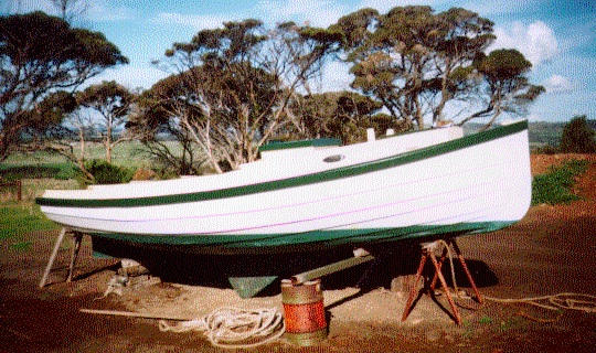
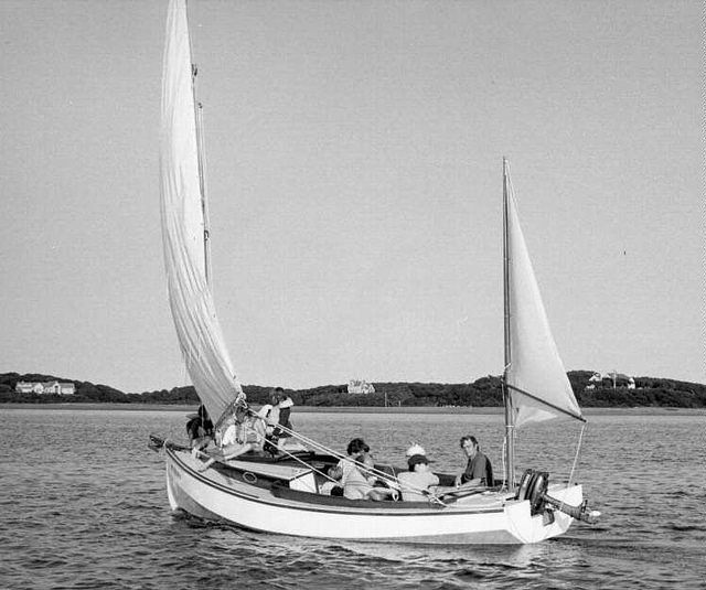
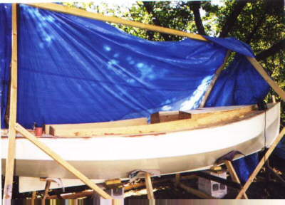
GINA – on Kangaroo Island, Australia
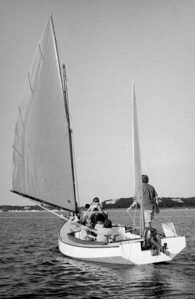
GINA

Colin Hunt, of Victoria, Australia, sent me this picture of GINA – Clive Colenso’s lapstrake Chebacco. He reports a good, dry boat which has been surveyed for charter hire. The waters around Kangaroo Island can get pretty rough. GINA has the cockpit modified to be self-draining with approximately ½ cubic meter of underfloor stowage for outboard, anchor etc.

Colin asks if anyone has the offsets for any version of Chebacco on a computer file in .DXF format? This might lend itself to CNC routing, to allow mass production of Chebaccos!

Chebacco –25 . . .

Simon Jones (also in Australia) reports:

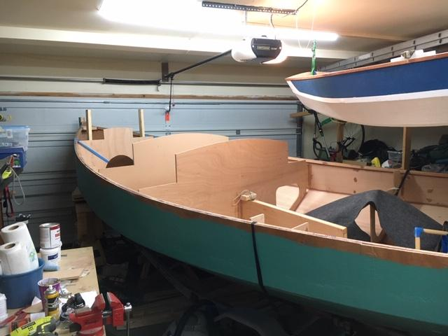
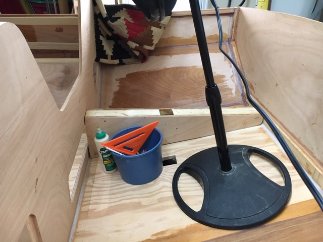
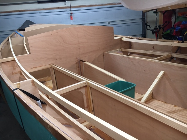
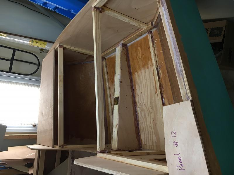
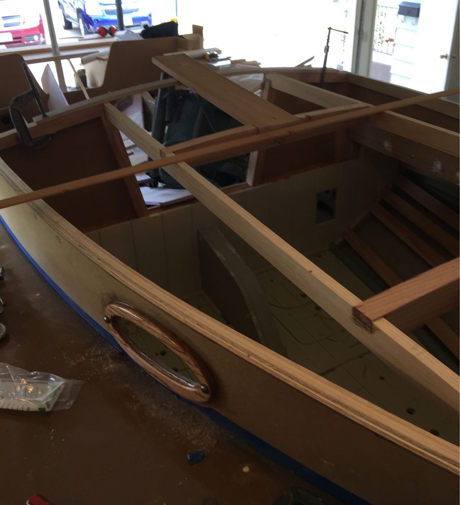
I’m building directly onto the bulkheads which I have moved to new stations , I am intending to rig her with a jib and a small bowsprit to accommodate anchors and larger foresails ( reachers etc, ) the interior has been enlarged to give full sitting headroom and quarter berths as well as a big double forard , taking out the centreboard has allowed me to cut the keel down to a flat keelson reducing draft and giving me a nice companionway to stand in with the hatch open , ( I’m just running thru all the alterations I can think of here ). I have closed in the cockpit at the stern to give me a large lazarette for storage, the cockpit is still 7′ long so plenty of day room … I have jumped up the deck height 6″ all round and instead of a flushdeck style cabin I have changed to the standard box cabin as in the 20 with a 5″ side deck (just enough for one foot, the other using the cabintop) while this is pretty thin its enough to go forard if necessary, however I hope to use

my forard hatch for most foredeck work . I’m keeping the mizzen as I have always found them to be worth every penny.

I’m currently epoxying everything as its obviously easier than doing it after construction, and I hope to have her in the water before the end of the year as I have the luxury of being able to work on her pretty much full time.

Your idea of having a Chebacco meet sound great! … I’d love to fly over to Canada and be in it…. That’s one fantastic cruising ground they have there and a chance to sail there should never be missed (falling in the water however is a one off!…. your firth would be warm by comparison) ok …I wont bash your ear about it all any more … I’ll be sure to get piccies to you when I have them.

Cheers Simon.

Well! This’ll be one interesting boat. As far as I know, it’ll be the very first Chebacco-25 to be launched. Watch this space!

Plywood – your views –

Tim Fatchen – yet another Australian, writes:

[WBS in Chebacco News #25
“So – Write to me about your ideas on plywood. I’ll fess up first – I
used pretty cheap Far-Eastern ply labeled BS1088, though it was
clearly nothing of the kind. It has frog-hair thin outer veneers, and
thickish inner ones. On the other hand the glue is certainly
waterproof and there are few if any voids in the inner veneers. My
theory is that glass/epoxy sheathing would make it acceptable, and
so far I’ve had no problems (3 years after launching). Let’s hear your
stories!”]

Bill, you clearly took the road favoured by the elite. From your
description of the plies, we fairly clearly used the same source for
Flying Tadpole in 1991, except ours was a grade down and didn’t try to
pretend to BS1088 (unless the BS stamp was added later to boost sales).

Nevertheless, still good waterproof glue and very few voids despite the
froghairthin outer plies. After seven years of abuse in Flying Tadpole,
the only problems which have arisen are two or three spots where
checking of the top ply has occurred (a series of slits about 1/2 inch
long, look like razor nicks) and we haven’t bothered doing more than
give them a lick of paint. Longevity was helped by through epoxy
encapsulation.

Our Nymph, even older (1989), was made from the same ply. Even more
abuse, sits for months at a time under the oak tree, gets roughly hurled
onto decks of houseboats occasionally, always makes landfall on sharp
stones lurking in the mud…Various nicks, dings and scratches in the
bottom, brutally neglected, but still absolutely sound (and originally 3
coats of epoxy inside and out, but no fibreglass).

In both cases, the ply was very heavy, though – I suspect mangrove wood
as the inner plies. Only real objection to it is that it’s a dog to work
compared with gaboon – splinters. I’m reminded of this as we’re still
using odd leftovers of 1/2 inch (not as good as the 1/4 inch was for
voids) as backing plates for deck hardware, battery boxes etc.

So that’s seven and ten years respectively of both use and neglect, the
latter being harder on boats…

Tim & Flying Tadpole

A few notes on the Chebacco’s properties

By Giuseppe ‘Pippo’ Bianco

Like most of the CN readers, I’m particularly intrigued by Phil Bolger’s designs and I have purchased plans for the Micro, Long Micro and Chebacco. The latter is very close to what I need: the most boat which conjugates sheet plywood construction, easy transportation, launching and hauling with a trailer, comfort and safety. I’ve not been able to find any data like righting moments and seaworthiness index for the Chebacco, so I decided to try to compute them by myself. After all, I’m a scientist by profession, so, I said to myself, this shouldn’t be too difficult… Well, that is true only in part. A complete analytical description of the interaction between a sailboat, the wind and the sea waves is almost impossible, and probably the only way to get comprehensive and reliable results would be building the boat, stuff her with instrument (like inclinometers, accelerometers, strain meters), sail it in a variety of conditions while recording the data, analyze them and draw the proper conclusions. I’m pretty sure that nobody carries out such measurements except maybe large, well funded designing companies working on super racers involved in world class competitions. So, in the amateur’s world, one is forced to use a mixture of common sense and a few empirical formulas.

A few basic numbers are needed to make a first assessment. Carl Adler (early readers of the Common Sense Design’s Newsletter will recall him as the Micro prototype builder) runs a great interactive sail calculator on the WWW which allows direct comparisons between any pair of sailboats listed in his database, recently integrated by myself with the relevant data for the Micro, the Long Micro and the Chebacco. The URL of his page is http://www.image-ination.com/sailcalc.html.

The parameters one needs to know for each boat are the length at water level (LWL), length out all (LOA), the beam, the displacement and the sail area. For the Chebacco those numbers read as follows (in metrics, yeah):

LOA=5.99 m; LWL=5.04 m; Beam=2.26 m; Displacement=789 kg; Sail area = 16.35m2.

The sail calculator crunches those numbers and rapidly comes out with the following sentences for our boat (compared hereafter with the corresponding data for the Micro and Long Micro):

Category: racer. Carl classifies the boats into four categories: racer, racer/cruiser, cruiser/racer and cruiser, in descending order of performance. Micro classifies as racer/cruiser, while Long Micro gets a cruiser score.

Capsize Ratio: 2.5. This number is an indicator of a boat’s ability to resist to the capsize: a value lesser than 2 is considered good; the higher the number, the more vulnerable is the boat. Micro gets 2.0, Long Micro 1.8, so both are stiffer than the Chebacco.

Hull speed: 5.5 knots . This figure depends only on the LWL. Micro 4.7, Long Micro 5.3.

Sail area displacement ratio: 19.5 . This is an indication of how powerful a sail plan is with respect to the vessel’s displacement. Values around 18 and higher indicate high performance boats. Micro gets 17.5, Long Micro 23.5.

Displacement length ratio: 170 (light). Micro sports a huge 411 (heavy), Long Micro an average 274 (moderate).

Length to beam ratio: 2.24. Micro gets 2.21, Long Micro 2.63. A value of 2.7 is considered average; 2.2 is low.

Motion comfort: 10.6. This numbers depends on a complex way from displacement, length and beam: the higher the number, the more comfortable is the boat. Micro gets 17.8, Long Micro boosts a 20.1.

Be warned that sometimes the ratios above are not plain ratios, but rather complex expressions involving odd powers of the parameters. A good description of the formulas used to compute the above parameters is given in  http://home.att.net/~hcyoung/formulas.htm

Well, the empirical formulas above confirm what the Chebacco sailors know already about her being spirited. Her capsize ratio is apparently not so good, such as the motion comfort index which is worse than the Micros’.

Not content yet with these numbers, my next step involved some more in-depth analysis. There are two ways to do that. The first is the old-fashioned one: grab a (modern) scientific calculator and a ruler, make measurements on the plans and compute the sought-for parameters, following algorithms commonly found in books on boat design. The second consists in modeling the boat in a dedicated computer program, which in turn will do all the number crunching. Commercial hull design programs are very expensive and barely worth the expense by an amateur: the free demo versions are, in my opinion, almost useless. Luckily enough, however, there are a few nice complete programs around, available free of charge on the WWW. The ones that I know better are Carene40 and Carene50 by Robert Lainé, Hulls by Gregg Carlson and Hullform 6S by Blue Peter Marine Systems. The Carene family is nice and robust, but it’s a bit lacking when one needs to compute the static properties of a boat. Hulls is great, with the only possible exception being the limited number of sections allowed to model a hull. Hullform 6S is probably the best and most complex, yet relatively easy to use, but unfortunately it doesn’t perform the plate development as the first two. On the other end, it’s not limited to hard chine hulls, and comes with a nice user’s manual.

I decided to use Hullform 6S to do my analyses. The first step has been to input all the sections as described in the table of offsets of the Chebacco’s plans. This is quite straightforward. I did that using the 42″ water level as baseline: the end elevation view of the resulting hull is shown in the figure below, where on the right half is the forward view and the left half is the aft view. The scale is in meters. This is very close to the drawings on the original plans, even if admittedly not perfectly fair. I didn’t consider the keel to keep things simple.

chebend (2)

Now, in order to perform the static analysis, one has first to balance the hull. I found that my synthetic hull balances very well (i.e. the pitch angle is very small) using the center of buoyancy positions given in the plans, with a few cm tolerance. Using a nominal displacement of 789 kg (1740 lbs.), the plans indicate a bottom draft of 0.193 m, while I find a bottom draft of 0.205 m. This is a difference of 12 mm. Alternatively, to sink the boat at the nominal draft, the displacement would have to be 710 kg (1565 lbs.). I don’t know which one is the correct number. Please note that this is the bottom draft (canoe body draft), not the keel draft.

The nice thing with Hullform is than one can compute the righting moment as well as other parameters for any heel angle. Let me warn you however that my analysis is oversimplified. It doesn’t take into account the combined effect of masts, sails, crew position, wave effects, and so on.

Another warning here: the righting moment computation requires knowledge of the position of the center of mass of a boat, around which the boat rotates when heeling. Longitudinally it has to be in the same position of the center of buoyancy, but the unknown here is its vertical position. This is tough to compute and actually, in the real world, it moves together with the crew and all the stuff on the boat. I first set the center of mass of the Chebacco on the waterline plane, but I’m not sure whether this is true or not. According to Bill Samson, this is a bit too optimistic, so, following his suggestions, I’ve performed the same calculations two more times, respectively lifting the center of mass by 0.1 and 0.2 meters.

Last warning: apparently Hullform treats any hull as if it was completely decked at the sheer level, even if there is no mention of this in the user’s manual. The Chebacco is not decked for a good part, so my results are optimistic.

Nevertheless, after 111 runs of the program, here are the plots of the computed righting moments with respect to the heel angle for three different vertical positions of the center of mass, referred to as VCG (vertical center of gravity).

Image6 (3)

My first (VCG=0.0 m) synthetic hull gets the sheer into the water at about 35 degrees of heel. It is apparently self righting up to about 115 degrees, but over that angle it goes all the way down to settle upside down. Looking at the numbers, there is no chance to right it back by pulling on the centerboard… Note also how the curves move downwards when VCG increases, indicating the well known effect of worsening stability. For VCG=0.1 m, the sheer at midships gets submerged at an heel angle of about 40 degrees, and the righting moment vanishes at about  degrees. Finally, for VCG=0.2 m, the sheer gets under water about 45 degrees and the boat is self righting up to about 95 degrees of heel.

An important number used to assess the stability of an hull is the ratio between the area under the curve with positive righting moments to the area over the curve where the moments are negative. In our first case (VCG=0.0 m), this ratio is about 2.7, reasonably good, but it goes down to 1.9 for VCG=0.1 m and to 1.3 for VCG = 0.2 m. After having computed these and several more parameters (actually Hullform does everything), one opens “Principles of yacht design” by L. Larsson and R. E. Eliasson at page 54, enters those numbers in the equations therein and computes a magic number, called the Dynamic Stability Factor (DSF). The Chebacco’s parameters for VCG=0.0 yield DSF=11, placing our beloved boat among the “inshore” vessels. This classification, endorsed by the International Standard Organization, classifies vessels into 4 categories following the water conditions they’re qualified for: sheltered (DSF<10), inshore (10<DSF<25), offshore (25<DSF<40) and ocean (DSF>40). The most penalizing for the Chebacco is the so-called Beam Displacement Factor, which apparently indicates that the beam of the Chebacco is too wide with respect to her typical displacement. However, increasing the displacement is not that effective in getting better figures for the DSF, and this apparently confirms that Phil Bolger and Brad Story are right (surprised?) when they say that additional ballast would be useless in the Chebacco. On the other hand, a slightly narrower beam (e.g. 2.0 m instead of 2.2 m) would have boosted the DSF to much more seaworthy values. The situation obviously worsens for VCG=0.1 (DSF=9), and for VCG=0.2 m (DSF=7). Hence, based on the above criteria, the 20′ sheet ply Chebacco is marginally qualified for inshore waters.

It needs to be said however that this flaming of the wide beamed boats came after the infamous Fastnet disaster in 1979, in particular because those boats are more easily capsized due to the action of big (b-i-g) and breaking waves and, when capsized, are more stable upside down. I don’t think that any Chebacco sailor would ever try to test his boat in really bad seas, so watch the weather forecasts… In any case, like Bill Samson said elsewhere in the CN, this reasoning is academic because there’s no notice yet of a Chebacco having been capsized.

Given the flared sections of the Chebacco’s hull, I tend to think that the computed DSF values are a bit underestimated, and I would conclude by saying that those boats “…are very good in rough water and forgiving in squalls and with prudent and skilled handling and not exceptionally bad luck would get over the North Sea, or the ocean for that matter; but by present day standards they are inshore and fair-weather boats”.

P.S.: for those who didn’t catch it yet, the last sentence is Phil Bolger’s opinion on his Chebaccos. I’m by no means an expert in boat design, and my speculation should only be considered as the result of a few pleasant hours of work of an amateur boat builder during a rainy week-end. Nevertheless, I would love to hear PCB’s opinion on this “paper”…

Bibliography

Lars Larsson and Rolf E. Eliasson 1994. Principles of Yacht Design. Camden, Maine: International Marine

Howard I. Chapelle 1936, 1994. Yacht Designing and Planning. 2nd Edition. New York, London: Norton

Philip C. Bolger 1994. Boats with an Open Mind. Camden, Maine: International Marine

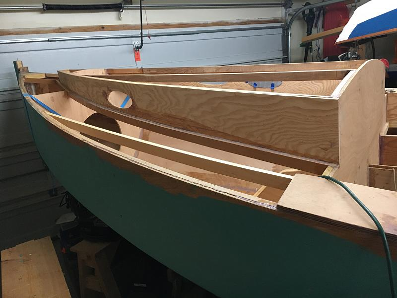
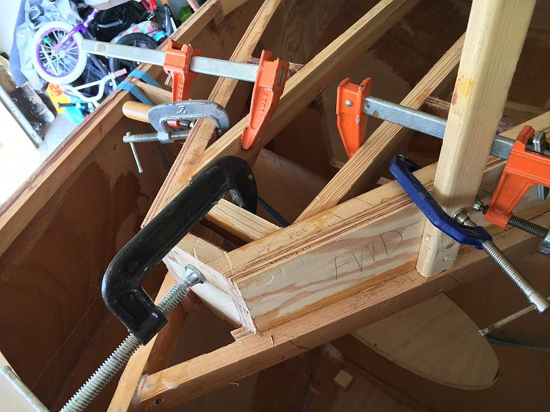
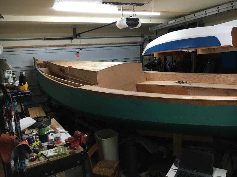
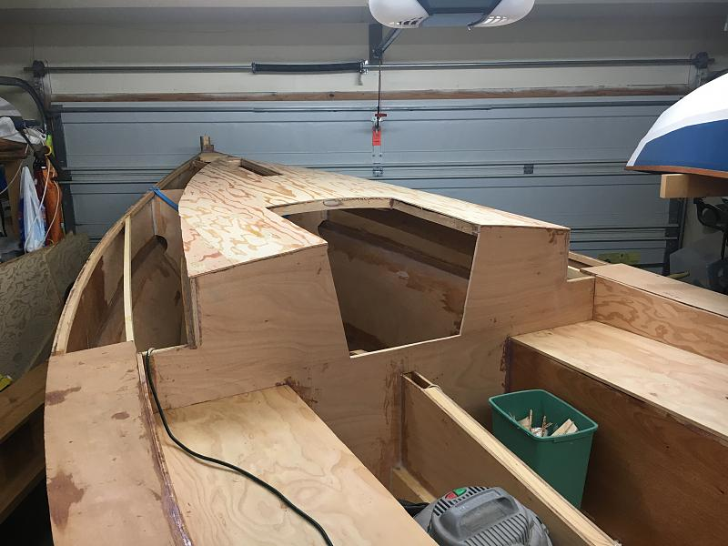
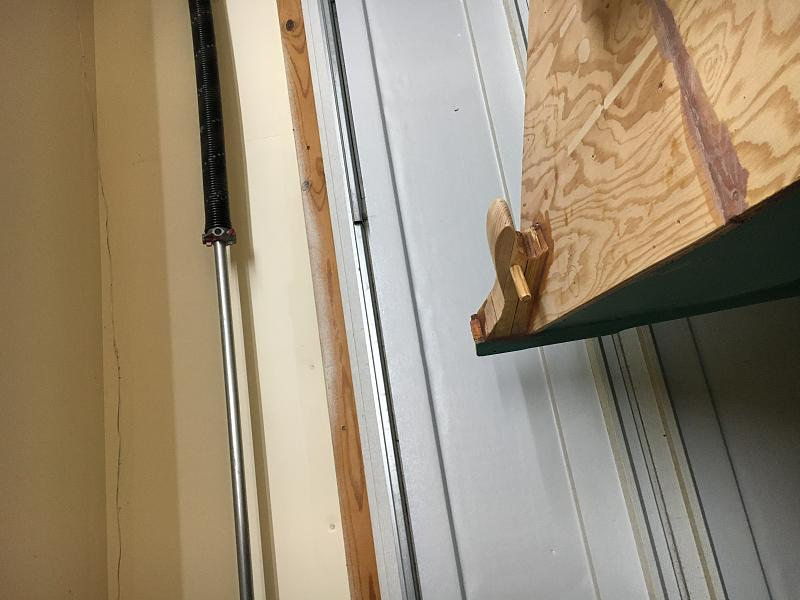
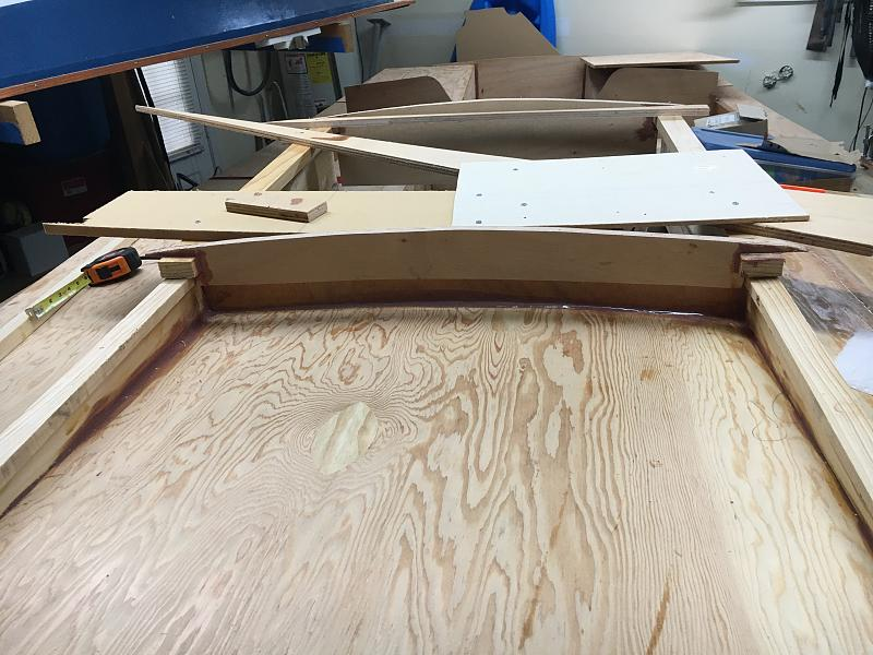
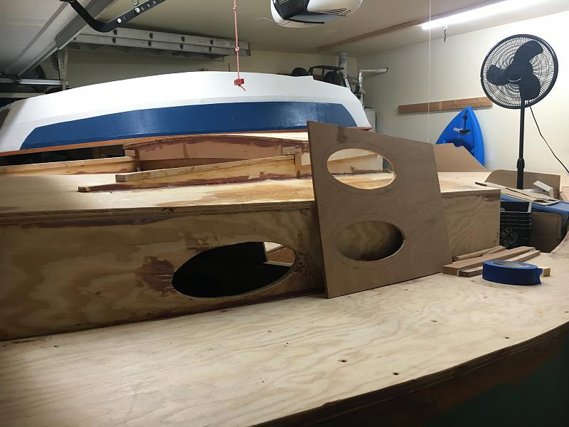
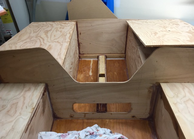
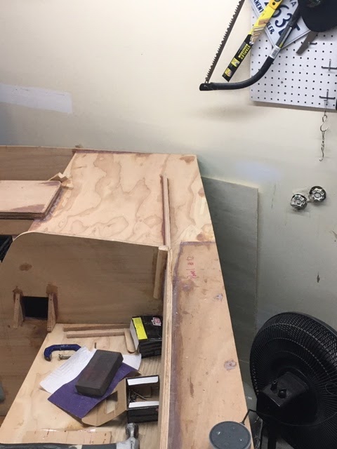
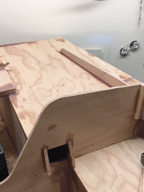
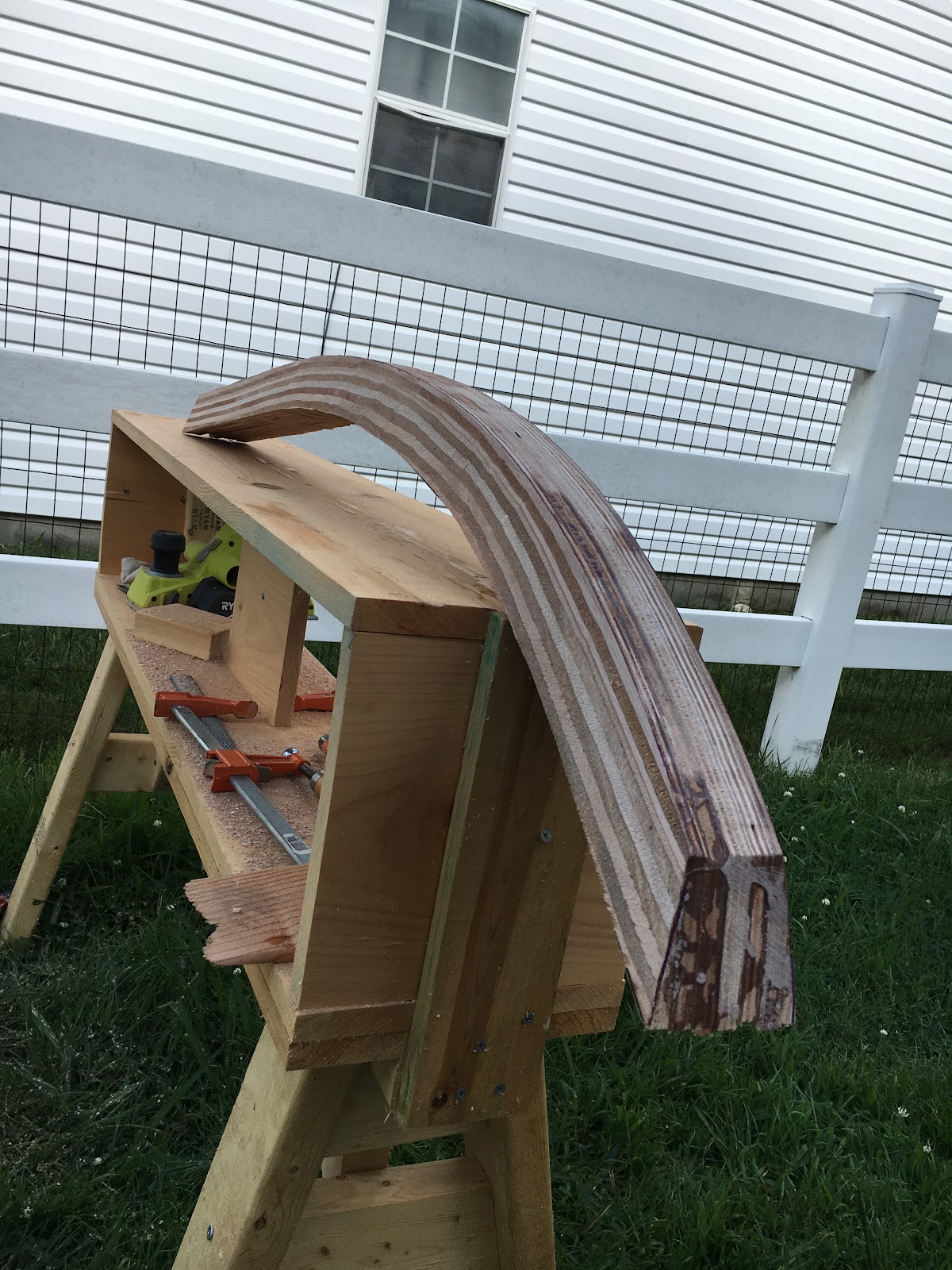
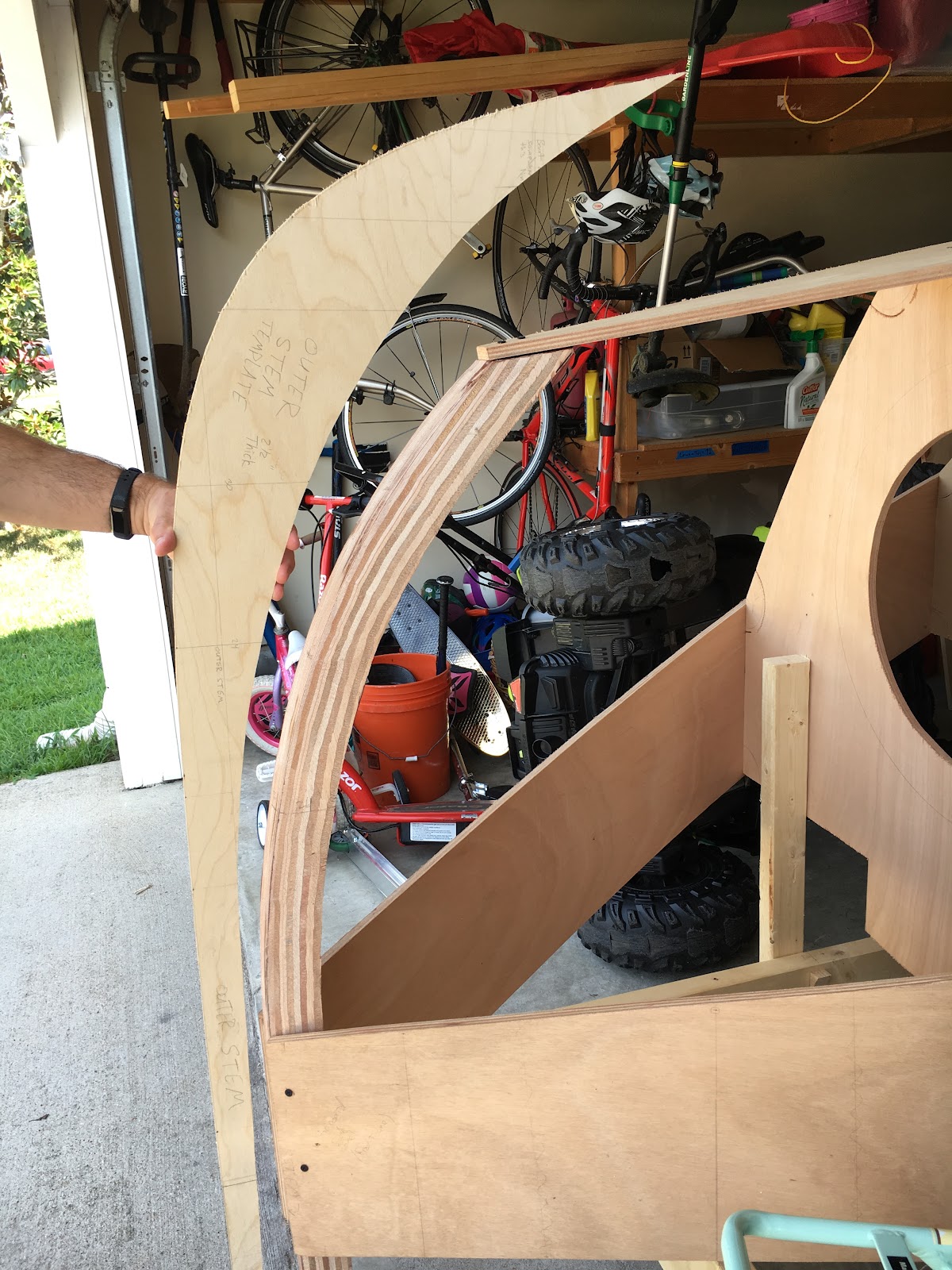
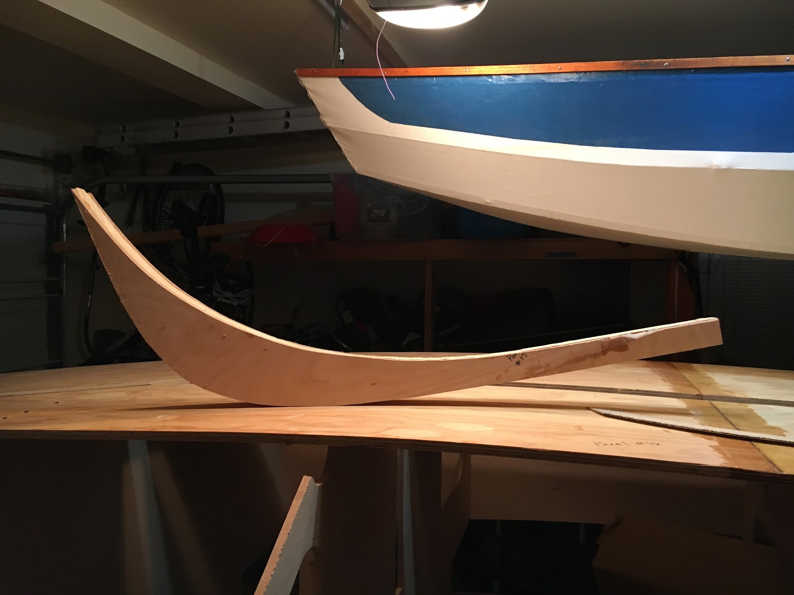
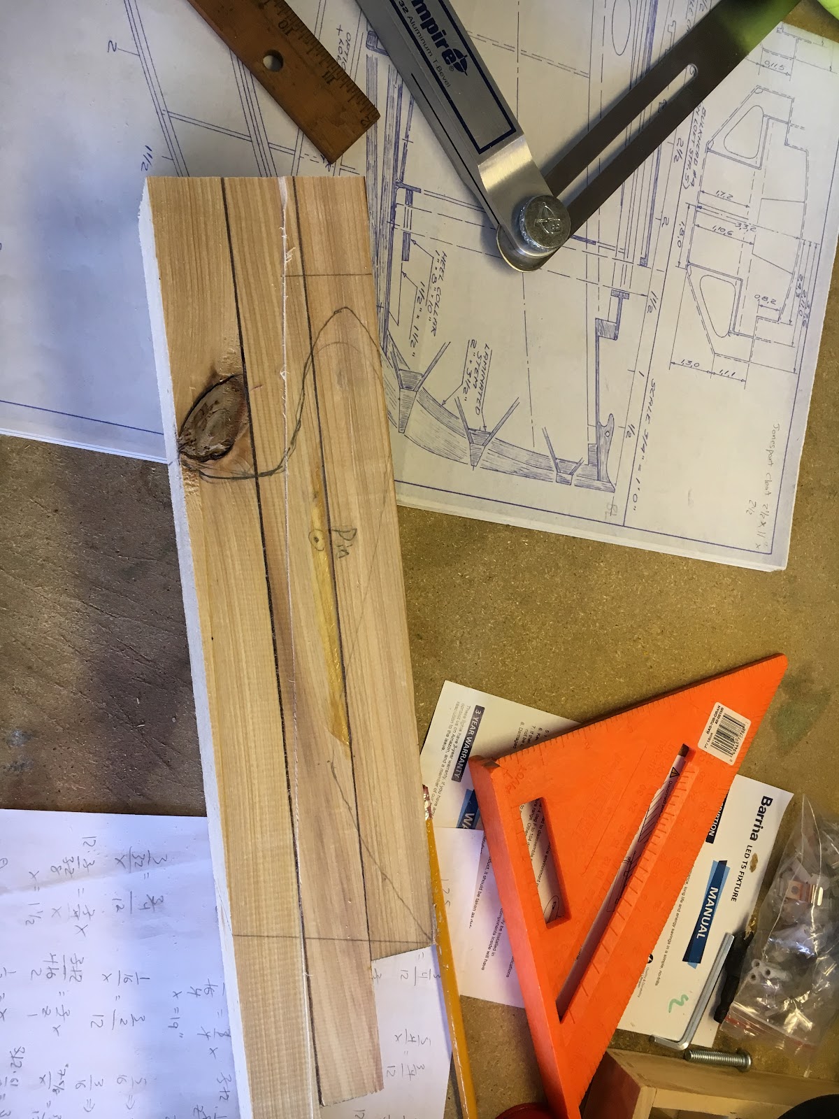
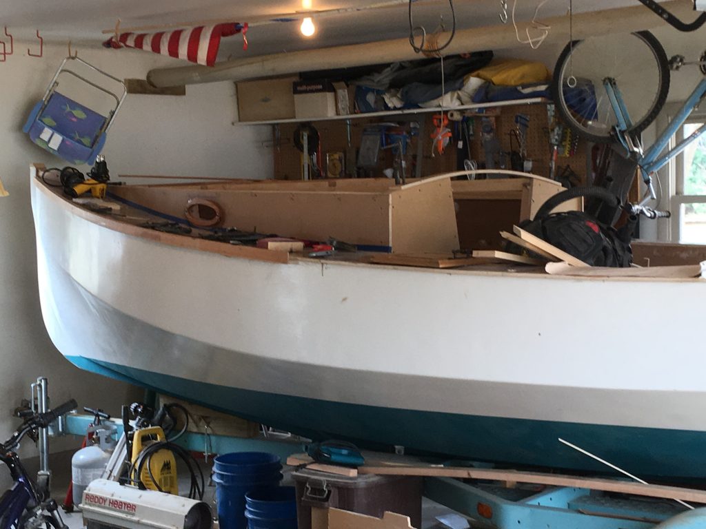
Tabernacle and Bowsprit

David Neder writes

I am located in the city of Waukesha, Wisconsin. About 90 miles NNW of Chicago
or twenty miles due west of Milwaukee/Lake Michigan.
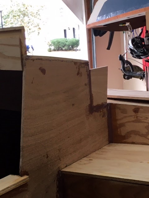
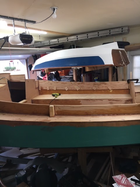
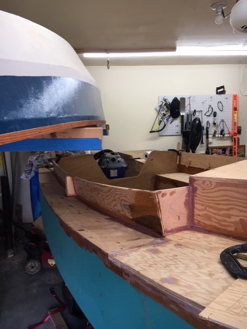
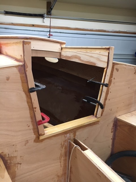
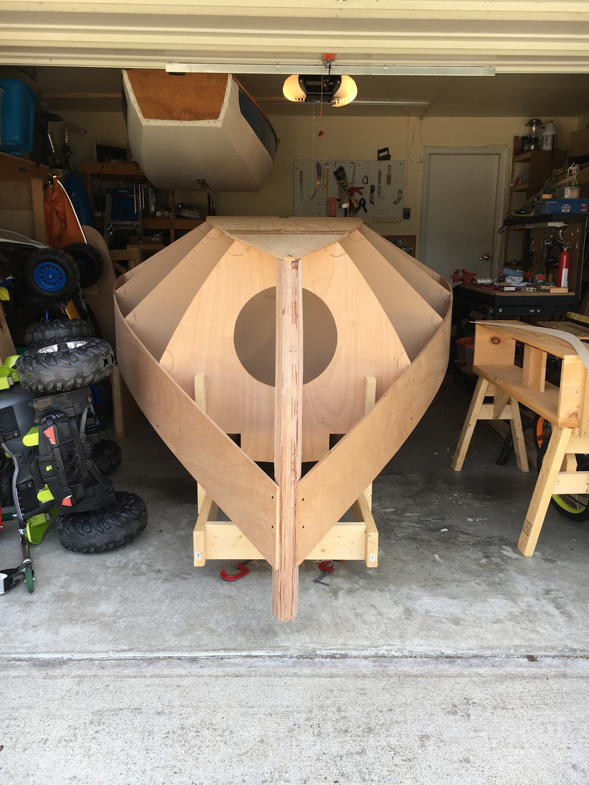
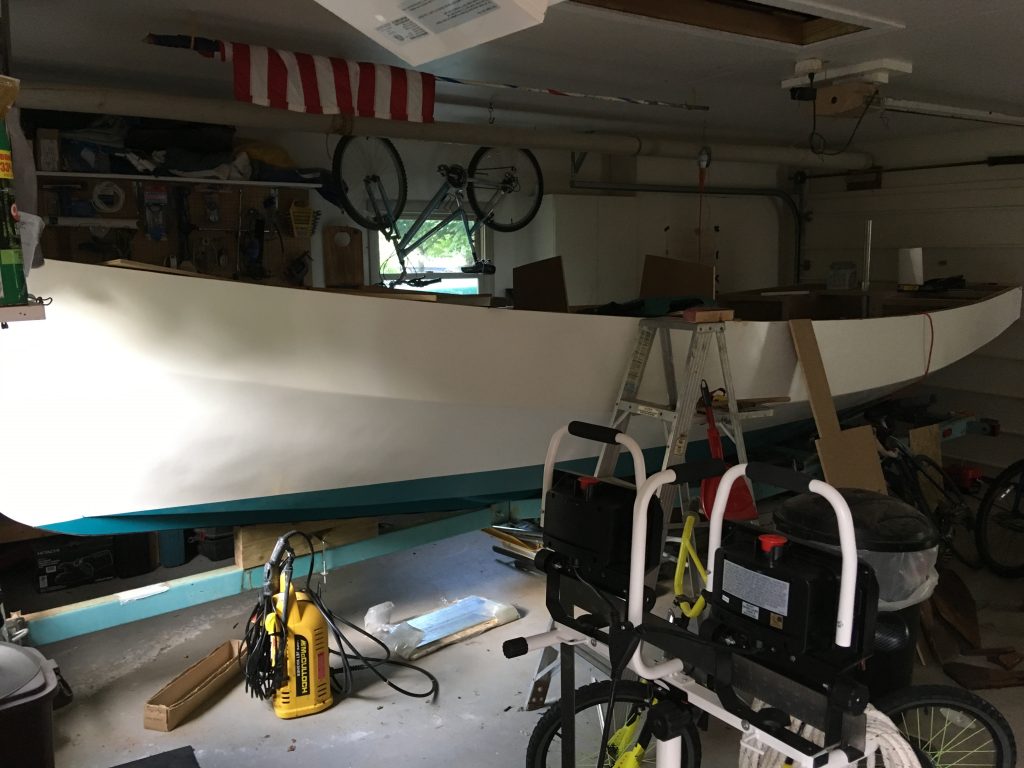
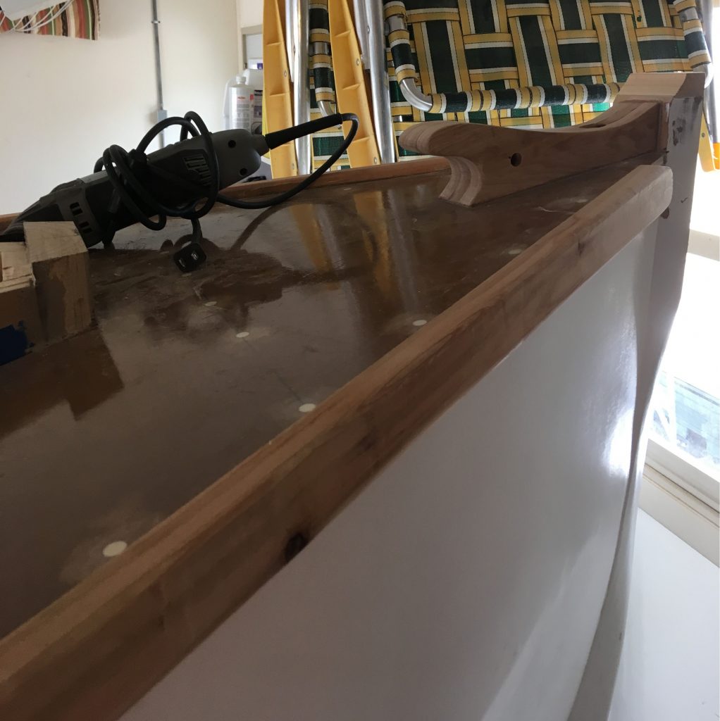
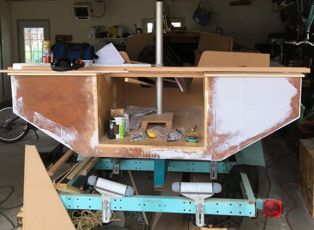
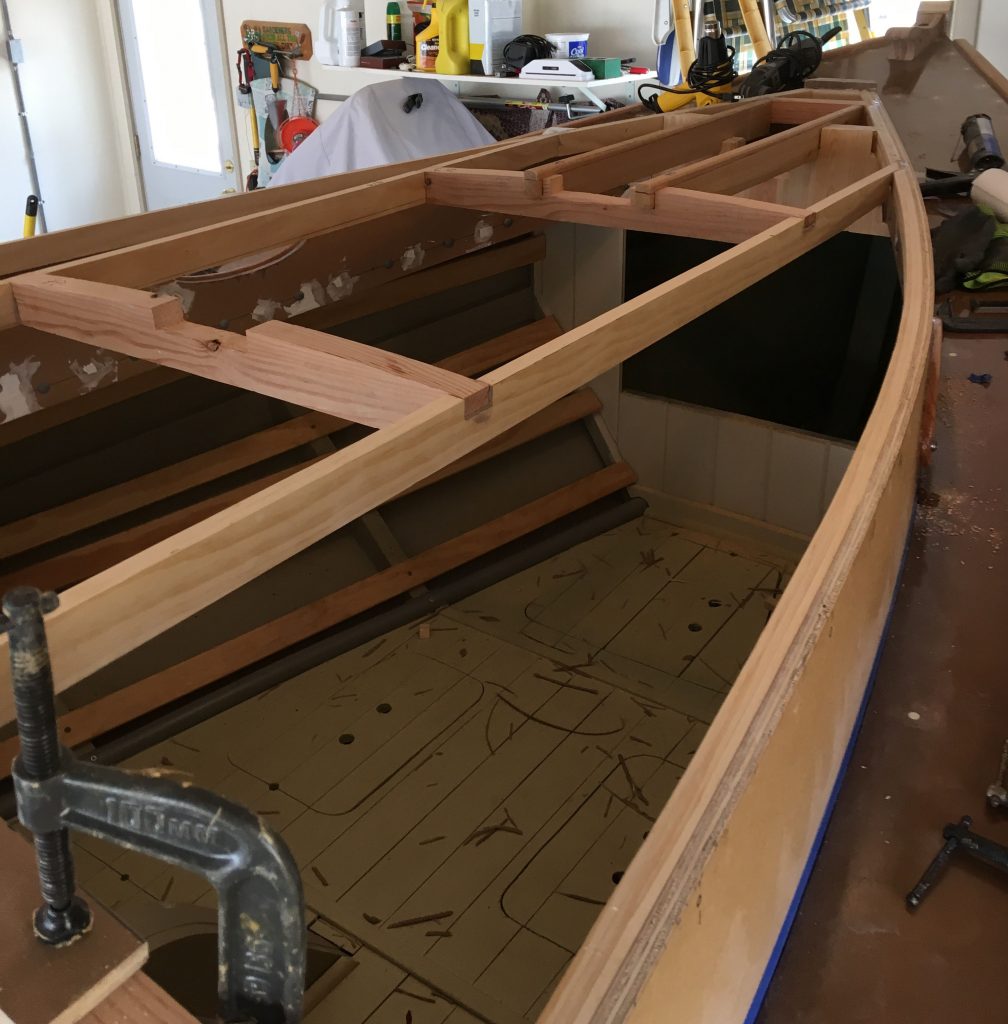
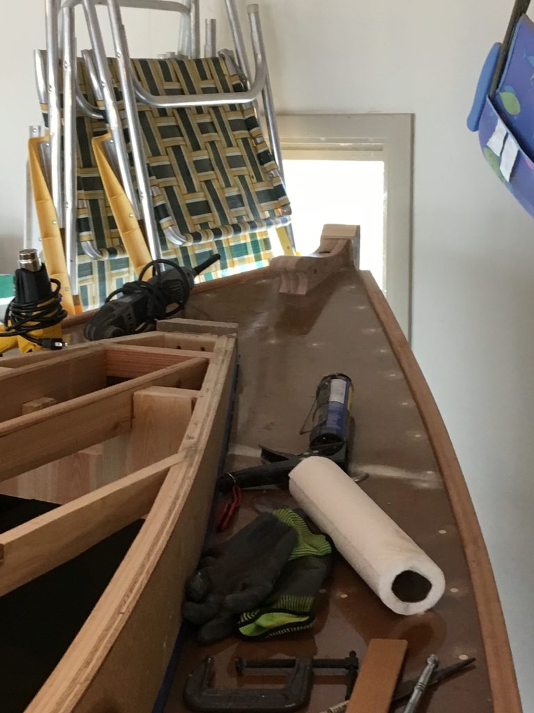
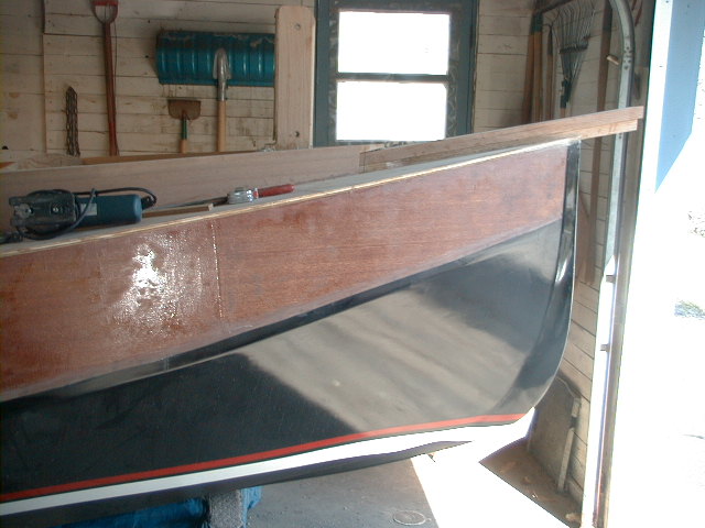
I am attaching photos of the “Anna C”.

Agf00001
Bow with tabernacle and short sprit.

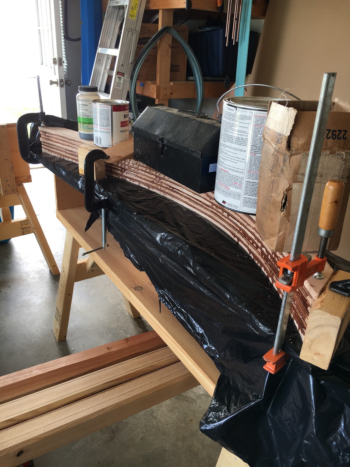
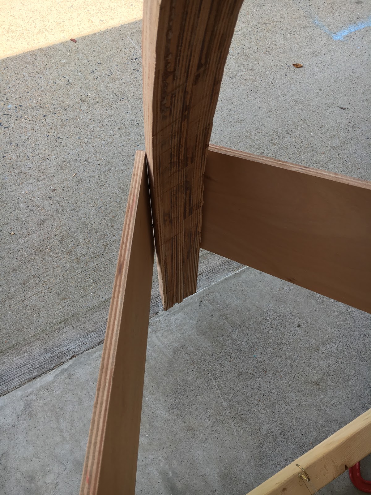
Since the boat will be trailered and I am too long in the tooth to wrestle with a mast, I added the tabernacle. Its section modulus in both the x and y axis is twice that of the mast at the pivot
point.


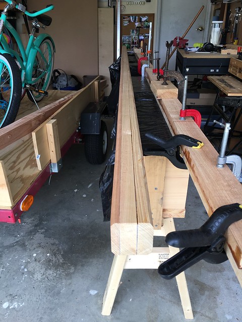
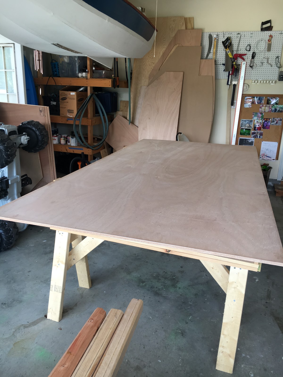
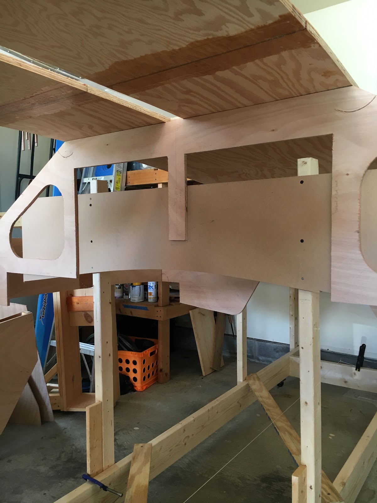
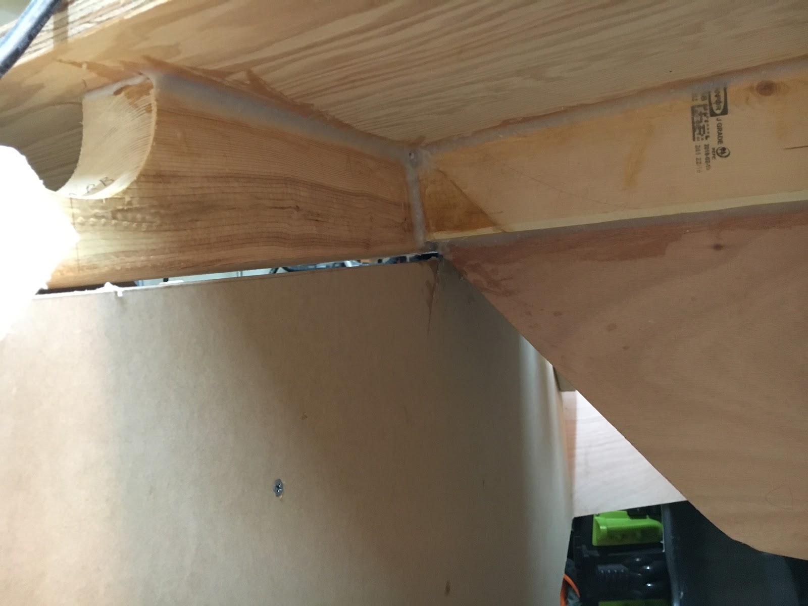
Materials: 1/2 Fir Marine Plywood, Ribbon strip mahogany plywood, mahogany, red oak, West Epoxy, Fiberglass. Two part poly-urethane paint on the exterior. Interior is paint with Acrylic paint with a fungicide. Construction is taped seam.

David J. Neder

And finally

David sent some other images, too, but there’s no more room in this issue. Neither is there room here for all the plywood-related comments, so they’ll have to be held over as well.

Please send your contributions to me, Bill Samson, 88 Grove Road, Broughty Ferry, Dundee, DD5 1LB, Scotland. wbs@sol.co.uk

Chebacco News 25

Chebacco News

Number 25, March 1999

ch246

Another glorious shot of Tim Smith’s LARK strutting her stuff off the New England coast. [Incidentally, these stunning monochrome shots of LARK have been just the lever needed by some of our readers to persude their better halves that the Chebacco is the perfect boat from them!]

Change to Web address:

Note that the World Wide Web address (URL) for Chebacco News is now

http://www.sol.co.uk/w/wbs/chebacco.htm

A Get-together for Chebacchisti?

I have been discussiong the possibility of a get-together for Chebacco-type people with various members of our elite [ahem!] circle, and it looks like the greatest concentration of Chebaccos is in the British Columbia area. I therefore asked one of the local guys, Jamie Orr, what he thought of the idea. This was his response:

Subject: Chebacco Gathering

Date: Fri, 11 Dec 1998 16:15:22 -0800

From: “Orr, Jamie” <JORR@oag.bc.ca>

To: “‘Samson, Bill'” <wbs@sol.co.uk>

Hi

I spoke to Jim Slakov and Randy Wheating last night. Both thought the

idea of a gathering was a great one. I expect something will happen

here anyway, and if we can bring in some other Chebacco and Bolger fans

from other areas, that would be perfect.

I didn’t take notes, but here’s what I think I heard. Jim’s boat is

finished and ready to launch come Spring. Gary Foxall, according to

Jim, has his boat turned and is working on the seams, the centreboard

case and so on. Randy’s boat is still upside down, but he’s moving

ahead too. Randy also corresponded a while back with someone in the

interior who was thinking of building — so there may be another boat

somewhere in the hinterland. He (Randy) thought that he could probably

be done by September of 2000 (see below), said it would certainly give

him a goal.

So it looks like there will be at least 3, probably 4 Chebaccos in the

water by then. Do you think its worth putting out feelers in Chebacco

News this early? As I said, there’s a strong chance a gathering of some

sort will happen anyway, and it would be good to meet some of people

from the Bolgerlist and the News.

Port Townsend’s Wooden Boat Festival is the first weekend after Labour

Day (the first Monday in September — does that hold true in Scotland?)

I don’t know if that would be a problem for potential attendees with

children, as school goes in the day after Labour Day.

Of course, having the Festival as a venue means that if only a few

people turn out, there’s still lots to do and see.

Jamie

PS Jim and Gary made their own sails. (All three of us bought the

materials at UK Sails in Sidney — 20 miles from Victoria on the way to

the mainland ferry — helpful folks.) Guess I’d better get a hustle on.

So there you are. If you’re interested, why not contact me or Jamie with your views?

Plywood?

I received the following email from Dr Dick Burnham, currently in Papua New Guinea:

Date: Sat, 13 Feb 1999 16:26:11 -0500

From: “Burnham” <burnham@datec.com.pg>

To: “Bill Samson” <wbs@sol.co.uk>

.My son is sending here xeroxes of the Payson-purchased sheet-Chebacco plans. I’ll study them and build a model. 1/16th inch ply–per your suggestions–if there is any here, otherwise I’ll just have to have some 1/16th rosewood or something equally exotic bandsawed for me to splinter and shove and glue up.

I was surprised by your suggestion to epoxy the interior side of the ply with 3 coats. The plywood is truly weather proofed; it is the baloney in a sandwich. No wonder some consider using non-marine grade ply. BTW, would you consider asking your newsletter folk to respond on what kind(s) of ply (and approx. cost/sheet) they used for the sheet-Chebacco? [OK guys – Fess up!] And how they arrived at their choice? It would be curious to see if you could construct a little chart on what, why, how much…even post-building analysis (such as: are they happy with it, does it have problems).

Now I see that the ply is so protected: glass cloth+3(?)coats epoxy outside, 3 coats inside. It still does more than merely make a form for glass, though. Or so it seems to me. It is structural and of course is in charge of resisting the log jammed into it on the water. Still wondering here about Parker’s use of “form-ply” which has US southern yellow pine exterior plys and has “waterproof” glues — after all it is a ply that must resist the sludge-like characteristics of wet concrete and must have sufficient

rigidity (better inner cores?) than other plys….

Regarding fiberglass. Has anyone tried Dynel, Xynole (I think?)? It is a highly abrasive resistant cloth that is knows to take kindly to curving forms…. Good for bottoms….

In your #23 you speak of Gray Feather as “having a bone in her mouth.” Just found in the delapidated library on this so tropical campus a copy of Slocum’s writings. Indeed he uses the very same phrase to characterize Spray as she turns from S. America and scoots westward with tradewinds to hold her leash onward toward Polynesia.

From deep in Melanesia,

Yours truly,

Dick Burnham

So – Write to me about your ideas on plywood. I’ll fess up first – I used pretty cheap Far-Eastern ply labelled BS1088, though it was clearly nothing of the kind. It has frog-hair thin outer veneers, and thickish inner ones. On the other hand the glue is certainly waterproof and there are few if any voids in the inner veneers. My theory is that glass/epoxy sheathing would make it acceptable, and so far I’ve had no problems (3 years after luanching). Let’s hear your stories!

Sails

The following email came from Jamie Orr:

Date: Wed, 14 Jan 1998 16:05:00 -0800

From: “Orr, Jamie” <JORR@oag.bc.ca>

To: “Samson, Bill” <wbs@sol.co.uk>

Lovely work, Bill

I was amazed at the quality of the print I sent in — are you sure you aren’t enhancing these things? My first thought was that we really have to get the cedar siding on the house refinished this year!

I hope to be able to send in some news on sailmaking soon. I’ve started with the mizzen, that being the simplest. I cut it out with straight lines all round and seamed it absolutely flat — as flat as my basement floor, anyway.

I’m using the two-sided tape to hold the cloths for sewing — I can’t imagine doing without it at this stage in my relationship with my sewing machine. It’s an old Pfaff 138 with a motor that never stops (or even slows!) and a hair trigger clutch. Even after using up two bobbins in practice, my first seams were still “interesting”. However, it’s gradually getting tamer, and the power is wonderful — the toughest

thing I’ve done so far is five layers of 4 ounce dacron in the clew patch, but the machine never noticed.

For holding the corner patches in place, I used a few strokes of one of the kids’ gluesticks. These are like lipstick tubes with soft quickdrying glue. It seems to stay flexible and doesn’t print through the cloth. To be on the safe side, I stuck each patch in the stack to the next, stuck the whole stack to the sail, then left some heavy books

on top for half an hour before running it through the machine. Of course, the books had to be the right sort — I found Chappelle’s “Boatbuilding”, Howard-Williams “Sails” and PCB’s “Different Boats” did a fine job. The last isn’t very heavy, but is definitely the right sort.

Again, great work on the News. Are you going to “bind” the last six as you did the first two lots? If so, put me down again for a copy.

Jamie

I replied:

Subject: Sails

Date: Thu, 15 Jan 1998 12:01:15 +0000 (GMT Standard Time)

From: Bill Samson <wbs@sol.co.uk>

To: “Orr, Jamie” <JORR@oag.bc.ca>

CC: wbs@sol.co.uk

Dear Jamie,

Some great ideas there! I used the double sided tape, too, on the main seams, and did all the edges, patching etc by hand.

I don’t know if you’ve tried some of the long seams in the mainsail yet, but here’s how I tamed the vast amounts of cloth –

1. Tape the next cloth on with double sided tape.

2. Roll up that cloth widthways, and the rest of the sail in the other direction, so you’ve got two long rolls (use tape to stop them unrolling) with a narrow strip of cloth

between where the seam is to be sewn.

3 Feed this long object through the sewing machine. The trick here is to get your sewing machine into the middle of the room with space fore and aft for the double roll as it passes through.

I hope that makes sense – anyway you’ve probably figured it out for yourself. I saw it happening in a photo I saw of a sail loft, where the machinist was working in a hole in the centre of a huge table which supported the double roll as it was fed through.

I like the idea of using the glue stick for patches. I used short lengths of double sided tape.

I haven’t done anything yet about a bound version of numbers 13 to 18. I only shifted about 3 copies of the first two, and it’s horrendous getting Word for Windows to

deal with documents that size, without falling over.

I’ve been working on an essay on how to build a Chebacco, for PCB&F. Phil’s planning to get essays from builders of various of his designs, and hopefully put them together into a book. I hope it works out.

Keep in touch!

Bill

sails

Me (Bill Samson) working on my Chebacco Mainsail – Very therapeutic!

For anyone planning to make their own sails, I’d like to recommend a couple of publications that I’ve found very useful:

“Sail Making for the Home Boatbuilder (Including: altering second hand sails)” by Paul Fisher – cost £12 +£1 p&p (UK) from Selway Fisher Design, 15 King Street, Melksham, Wiltshire, SN12 6HB, UK, www.selway-fisher.com, email: selwayuk@aol.com

“The Sailmaker’s Apprentice” by Emilano Marino, International Marine (McGraw Hill). $39.95

Ed Heins makes progress:

Had a photo and email from Ed Heins, who is completing a Chebacco starting with a part-built hull from Burton Blaise:

ch248

Ed Heins’ Chebacco hull nears completion

Subject: Winter’s waning

Date: Sat, 20 Feb 1999 22:16:50 -0500

From: “Ed Heins” <edheins@hcr.net>

To: <wbs@sol.co.uk>

Bill,

Haven’t messaged you for a while and thought I’d give you an update on the project. The boat still resides beneath 2 tarps and lowered A frame in the back garden, but I do have posession of spar lumber as of today. The local sawmill was cutting some spruce, so I commissioned a half dozen 2 x 6 ” 20 footers and another dozen 14 ft 1 x 4’s. He wanted to cut me a 4 x 4 blank, but I think laminating will help stop warp. Corkscrew masts being just so unprofessional looking.

Lamination starts on Monday, and then will be working on turning the square blanks into round masts. Oh well a first time for everything.

. . .

Cheers,

Ed

And finally:

A slightly thinner Chebacco News than usual, and later than usual, too! Don’t complain – It’s up to you guys to keep me informed of developments. No news = no Chebacco news!

Bill Samson, 88 Grove Road, Broughty Ferry, Dundee DD5 1LB, Scotland.

wbs@sol.co.uk