Chebacco News 22

Chebacco News

Number 22, August 1998

syl2

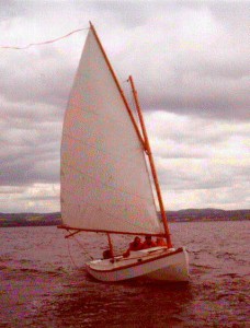
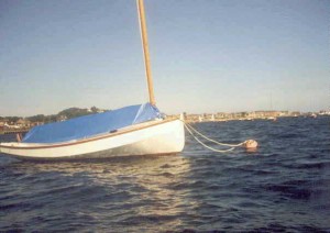
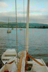
SYLVESTER heels under an ominous sky

Photos?

You must be getting fed up of pictures of SYLVESTER under sail. How about you Chebacco sailors sending me some of yours? Of course, I appreciate that it isn’t the easiest thing to get photos of yourself underway. The above one was taken by a friendly powerboat driver, to whom I had thrown my camera and asked to shoot off the whole film. On a different occasion, I got my crew to sit at anchor in a tender with the camera while I sailed around him. It’s seldom possible to get good close photos of a boat under sail from the shore, unless a long lens is used.

Two-part Paint

Jamie Orr, whose Chebacco is nearing completion, sent the following email to the ‘Bolgerlist’ discussion group on the internet –

A few months ago I was asking for your experience with paint. I got a number of good responses, with recommendations ranging from latex to two part polyurethane. My concerns were that the finish have good resistance to abrasion, which favoured two part paint, and that the paint be reasonably user friendly, which didn’t. I viewed one part polyurethane as a possible compromise. Prices ranged from $15/litre for enamel to $29/litre for one part polyurethane to $40+/litre for two part.

I finally decided to go for two-part paint. Here’s what I learned using it, in case someone else is in the same boat (no pun intended). I found the paint to tack up quickly, but it wasn’t really that hard to use. I used a West system foam roller to apply it, followed quickly by a foam brush, brushing back into the already painted part. The hard chines of the Chebacco made for easy dividing lines — I painted the keel, then each bottom side, then each bilge side. (I’ve left the topsides for later, after

the deck joint is glassed.) This split the job into long narrow panels, making it easier to keep a wet edge on the paint.

Two things to watch for.

I found that an area about 2 ft by 2 ft was big enough to roll at once. If I did much more, the paint started to tack up before I could brush it all out — I used a three inch disposable foam brush, and didn’t brush any area more than once if I could avoid it. I estimate I had 20 seconds to get the area brushed. I also found that I did a better job if the brush stroke was backhand, not forehand. That meant I painted while moving from right to left, brushing back left to right (for a right-hander). I also changed to a new brush every so often. One roller cover did a full coat.

The other thing to avoid is to leave a roller edge mark across the end of the already painted part — its *very* hard to brush out. To cover the surface, I like to roll first one way, then go over it again at 90 degrees. To avoid leaving a mark, I rolled the paint first parallel to the wet edge, but not touching it — leaving an inch or two uncovered. Then when I rolled at 90 degrees, I rolled back into the wet edge, just as with brushing. The inch or two space only gets rolled one way, but it covered okay, and the join with the previous part was invisible after brushing.

Any flaws have to be covered within that estimated 20 seconds, or the fix will be as bad as the flaw. I put on one coat of primer, and two finish coats, so I had two “practices” before the final coat.

After the cost, the biggest drawback is the toxicity of the paint. An organic filter mask is a minimum requirement, and the paint should not be allowed to touch the skin either. I wear a beard, and so its hard to get a good seal around the mask. To help this out, I globbed vaseline into my beard and put the mask on/in this. If you try this, waterless hand cleaner will get the vaseline out again, eventually. Gloves, sleeve protectors and disposable coveralls completed the outfit. Safety glasses might be a good idea in case of splashes, but I can’t wear them with a mask as they fog up.

For cleanup, I just leave the roller cover and brushes until the paint cures, then throw them out. The solvent is about as toxic as the paint, so I haven’t used any yet. To clean up the mixing cups, I slosh the dregs of the paint in them to catalyse everything, then chuck them when cured. I also use disposable plastic liners in my paint tray, and found out that this paint will eat its way through eventually, so make sure the tray underneath is clean as well.

I used Endura paint, made in Edmonton, Alberta. For information go to:

http://fn2,freenet.edmonton.ab.ca/~bobstory/endura.htm

They have a wide range of colours, or will match any sample. The literature mostly talks about spraying, but they have a special brushing component to replace the usual catalyst if you want to brush or roll it. Make sure the pigmented component is well mixed — preferably shaken on a paint store’s mixer. I found the paint did not change or start to gel while I worked. I mixed up a full litre of primer, but used smaller batches of finish coat —

I mixed about 300 mls (9 oz) each time, adding it to the old stuff in the paint tray. This was to avoid having a lot left at the end.

I had no problem with sagging, but found that if I dripped on an unpainted spot, I had to smooth it immediately, or the drip showed through. I guess the 20 second rule applies here too. After the primer coat, I masked the bottom and bilge surfaces separately, so I could leave them covered while I did the keel, then leave the bilges covered while I did the bottom. More preparation time, but it worked.

There it is. Required care, but wasn’t that hard to use after all.

Jamie Orr

Reefing tips

Craig O’Donnell sent me the following email, pointing to reefing systems described on the Internet:

Speaking of reefing, you kight want to consider the pointer to:

http://www.friend.ly.net/user-homepages/d/dadadata/canoe/vaux.html

for the next issue. While it isn’t Chebacco-specific, it’s a good overview

of 3 reefing schemes. The originals were (are) for battened sailing canoe

sails, but of course modern lightweight battens could be used on a Chebacco

sail instead.

In any event it might spark a brainstorm among the Chebacco Riggers of the

world.

Sail-making, rigging etc.

Jim Slakov is making his own sails at the moment, and sent me a number of questions. Here’s my reply:

First of all, grommets – I used the cheap brass ones that you’ll find anywhere – 1/2″ inside diameter for everything. I agree that they’re nothing like as good as the ones used by professional sailmakers, but they don’t need special equipment either. I’ve used them on sails for the past 10 years and they’ve lasted fine, apart from a bit of greenness!

The way I fit them is to sew the ring part into the sail, with strong thread, until you can’t see the brass – Then I put in the grommet and flatten it out with the punch and anvil you get with the grommets. It seems to be plenty strong enough. An alternative is to go to an awning maker and get him to press some in – Still it’s nicer to be independent! If I ever make more sails, I may treat myself to some professional kit, but it’s hardly worth it for one set.

You also have some questions on rigging. Here goes.

1. Is there a particular point on the boom to attach the topping lift? Is it just tied onto a cleat or an eye?

– If you look at the gaff sailplan sheet that is part of Phil’s set of drawings, you’ll see that the boom has eyes at various distances from the end of the boom These are, in order:

12″ in from end – The attachment point for the mainsheet block.

8 1/2″ in from previous eye – fairleads for clew reefing pendant (first reef).

19 3/4″ in from previous eye – fairleads for clew reefing pendant (second reef)

8″ in from previous eye – attachment point for topping lift.

17″ in from previous eye – attachment point for second mainsheet block

I have my topping lift tied onto the boom, and going through a block shackled to an eyebolt near the top of the mast, then down the mast, through a block on the deck, via a fairlead, to a cleat on the cabin top (port side). If I was doing it again, I’d probably go for the simpler solution of tying it at the top of the mast and simply cleating the other end on the boom, via an eye.

My only deviation from Phil’s drawing is that I have the reefing cleats much further aft, so that they are easily reached from the cockpit. I keep the pendants in place all the time – including two at the tack. There are four cleats in all – one for each pendant. The pendants are 1/4″ braided line. The pendants cleat on the starboard side of the mast so that you can reef down on starboard tack – giving you right of way over other sailing boats. Cunning, eh?

2. How is the peak halyard attached?

The gaff has a strop (1/4″ dia rope, in my case) going from the mid-point to the top. This should be tied as tight as possible – It looks loose on the sailplan, but you’ll find it falls away like this even if you tie it bar-tight. A shackle slides back and forwards along this strop and the peak halyard is attached to this shackle. This means that when you have the full sail up the shackle will be near the foot of the strop, but when you take in reefs it will be further up, so that the pull is still at right angles to the gaff, allowing you to peak up the sail nicely. Both halyards go through blocks shackled to eyebolts near the top of the mast, then down to turning blocks at deck level, via fairleads to 6″ cleats on the cabin top (starboard side).

3. How do you attach the throat halyard to the gaff jaws?

Interesting one this. I originally shackled it to a lashing on the gaff, but soon found that the shackle was wearing a nice groove in the mast when the sail was peaked up. The best thing to do is sew an eye in the halyard and lash this directly to the gaff jaws (- I have holes drilled in the jaws to accommodate this lashing, as well as the sail lashings).

4. What about the forward end of the boom?

The weight of the boom is enough to keep the luff tight when the sail is raised. No need for any downhaul or vang, in my experience.

5. How do you tie the jaws (boom and gaff) to the mast?

There are holes in the ends of the jaws and I have 1/4 lines thread through them with wooden beads (‘parrel’ beads) to help stop them binding and stopper knots (figure eight) at the ends. The correct tension in these lines is determined my trial and error when you first raise the sail. Some builders have used a conventional gooseneck fitting for the boom.

6. How is the forward end of the sprit boom attached?

There is a line (the ‘snotter’) tied in a hole at the for’ard end of the sprit boom which goes up through a block lashed about 1/2 way up the mast, then down to a 4″ cleat. This supports the sprit boom, and flattens the sail when it is tight. There is no other attachment point for the boom, except for the lashing to the clew. It is important to keep the mizzen flat. If it draws too much you will get weather helm. If you look at Phil’s sailplan drawing the arrangement should become clear.

7. Can you hang onto the tiller while adjusting the halyards underway? Do you use a tiller extension?

No – I normally heave to. This involves centring the mizzen to make the boat point into the wind. Then you can adjust everything at your leisure! I don’t use a tiller extension, but it could be useful at times.

8. What is the sequence for setting sail?

(a) set up the mizzen so you are head-to-wind.

(b) take up the slack in the topping lift and peak halyard so the boom gallows can be removed.

(c) keeping the gaff roughly horizontal, pull alternately on the peak halyard and the throat halyard until the boom jaws rise and the luff is tight.

(d) pull up the peak halyard until the creases run from peak to tack. This is critical for windward performance. A crease from throat to clew means the top part of the sail isn’t drawing properly and performance will suffer greatly. I occasionally need to peak up the gaff during an outing when the halyards settle down.

(e) drop the centreboard if you are heading out to windward.

(f) cast off, backing the mizzen to send you off on the desired tack.

(g) sheet in, and you’re sailing!

I look forward to seeing photos of your boat when she hits the water. The thought of 3 Chebaccos [Jim Slakov’s, Garry Foxall’s and Jamie Orr’s] sailing in company in B.C. waters is wonderful!

Cheers,

Bill

Scuppered hatches?

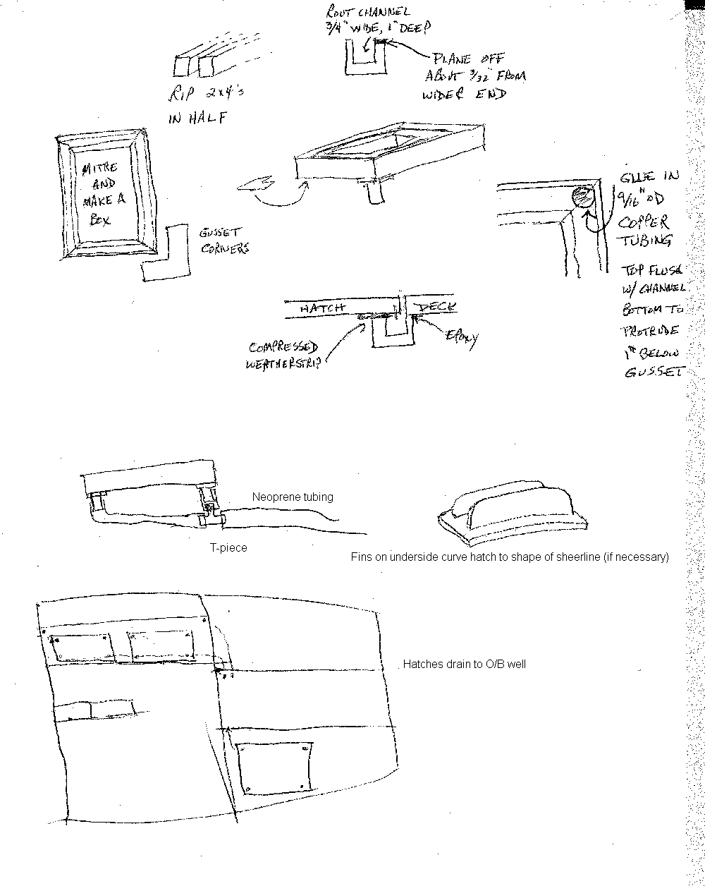
Gil Fitzhugh has decided to put hatches in his Chebacco – in the seats, and at either side of the outboard well. He wants them flush (for comfort, and appearance sake) and doesn’t want them to be a source of leaks. His solution is to provide self-draining ‘ledges’ for the hatches to rest on. These have a gutter and drain holes at the corners which lead water away to the ouboard well, where it will drain overboard. This sketch is pretty much self-explanatory

gildrg

Wanted – a Chebacco

I had an email from Patten Williams, of Augusta, Maine: <togus@mint.net>

I’m looking to buy a used Chebacco and haven’t seen any in the usual places

I look to find boats for sale. Can you direct me to a place I might find

used Chebaccos?

If you know of any, then you could contact Patten by email, or alternatively let me know, and I’ll pass on your message.

Floorboards – to seal or not to seal?

Ed Heins was asking whether the cockpit sole should be sealed, keeping a watertight volume under the floorboards. Here’s how I replied:

As far as I know, all Chebaccos (mine included) just have loose floorboards here, and pump out the underfloor area from time to time. That way, any stray water sloshes around below the bit you are standing on, and doesn’t make it slippery. I’ve used plywood for the loose floor, in three parts – one either side of the CB case and the other covering the aft section. Brad Story has used pine boards, with narrow gaps between. He screws them down but leaves room to poke the end of a hand pump for emptying the bilgewater.

Have you read Sam Devlin’s book on stitch and glue boatbuilding? He favours your method, as it adds strength, but he fills the void with foam and still leaves a drainage channel for getting stray water out.

Incidentally, I’ve had a little trouble with water lying in that free-flooding area

aft of the cockpit. A couple of little limber-holes that drain into the cockpit wouldn’t go amiss. I plan to drill some next maintenance season.

And finally

That’s all for this issue. Please keep your news, photos, stories, questions etc coming in.

Bill Samson,

88 Grove Road,

Broughty Ferry,

Dundee DD5 1LB,

Scotland

wbs@sol.co.uk

Chebacco News 21

Chebacco News

Number 21, June 1998

syl1

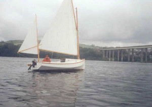
SYLVESTER scoots along in a sea breeze

Why so late?

You’ve probably noticed that this issue is about a month later than usual. The explanation is that there wasn’t enough material from our readers to fill an issue until now. Anyway, there’s some good stuff now, so I hope you’ll find it’s been worth waiting for.

Reefing (again!)

I’ve made some very simple modifications to the reefing system on SYLVESTER that make reefing under-way a much more managable process. In essence, all I did was to move the horn cleats for the pendants to a point about mid-way along the boom; making them easier to reach without leaving the cockpit. The pendants at tack and clew are left in place at all times, and just hauled in (tack first) as the occasion demands, just as Brad Story described a few issues ago.

I had a chance to try it out in anger last weekend; I took in a reef when things got blustery, and shook it out again when things quietened down a little. It worked very nicely.

Building the Coach-roof

Builders tell me that one part of the plan that takes a lot of thought is the construction of the coach roof. Here’s how I did it.

First of all I put on the cabin sides – just cutting and trying until they fit, not forgetting to cut the elliptical holes for the windows before finally gluing them in.

Next job is the framing for the roof – not too difficult joinerywise, but it takes a bit of study of the drawings to figure out what’s needed, allowing for the right clearances for the mast slot and hatch hole.

This is all faired up in preparation for the top going on.

I made the top from 1/2″ ply – it takes a LOT of bending – Two layers of 1/4″ might be easier. The top is made in two halves – port and starboard. I glued and screwed it to the centeline first – LOTS of screws to make sure it stays down.

I found, when bending the curve into the top the framing started to sag, so I placed some temporary props between the framing and the bottom of the hull to try to minimise this sagging.

I then applied glue to the rest of the framing and applied my full 180+ pounds around the edge as I put in the screws. This is the hardest bit, because if you stop half way through, with not enough screws in, it’ll just pull out and spring up. I’d recommend a screw every 4 inches or so.

Finally I removed the props and there was a little sag in the roof. No big problem, but it does mean the hatch sides need to be convex along the bottom and require a bit of fitting. Once the hatch sides are on, and the framing of the mast slot, the whole thing is as stiff as you could wish for.

I hope this is helpful.

framing

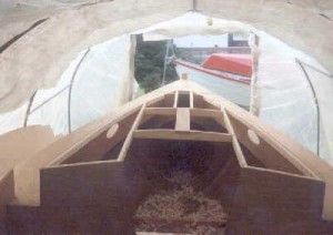
Cabin sides in place and framing for the coach-roof completed

Jamie Orr Pours Lead in his Centreboard

Jamie writes:

Here are the lead pouring pictures.

First, some reminders:

  • Pick a dry day or work under cover. Molten lead will splatter if it contacts moisture.
  • Clean up your work area. It’s obvious from the photos I could have done a lot more in this regard. (Also, I think we could have had the stove in a less vulnerable position, so it couldn’t be easily knocked over. On the other hand, it didn’t get knocked over, and was at a convenient height. Take your pick.)
  • Lead stays hot for a long time, watch your fingers.
  • Wear protective clothing, and don’t breath the fumes.

Now, what we did.

We drove four big nails into the edges of the hole in the centreboard to anchor the lead. This was only just barely enough, and the lead was a bit loose after it cooled and shrank. Some epoxy around the edges fixed that.

A piece of steel plate was clamped to the underside of the board. I wire brushed the plate as it was a bit rusty, but didn’t do anything else. The books favour some blacking or soot, as well as preheating the steel, to prevent the lead from sticking, but we had no trouble with it. The board was carefully levelled on sawhorses.

The lead had been previously used to seal the removable top on a 45 gallon drum, so it came as a thick strip about an inch thick. Dad bandsawed it into chunks while I set up the board. We fired up the backpacking stove, put the pot and lead on, and put a 3 lb coffee can over the whole thing (both ends cut out of the can!) with an air space at the bottom. The can acted as a heat reflector, wind shield, and chimney for the stove, greatly increasing the heat to the lead.

It took about six minutes to melt 2/3 of a pot of lead, or about 6 lbs. Beeswax is supposed to help impurities float to the top of the lead, but they seemed to float up quite well without help, so I didn’t bother with the wax after the first lot. A tongue depressor removed the dross nicely. I found the easiest way to hold the pot was with vise grips, ignoring the bail, at least for this pot. (The pot was bought originally for bullet making, from a sporting goods store.)

I didn’t pour the lead all at once because I only had a small stove and pot. Because the first (learning) pour was on the small side, we had to do a very small fourth pour. Also, this last pour was delayed, so the lead already poured may have cooled a bit. In any case, this last, fairly thin pour didn’t bond as well to the already poured lead. When I started to level the excess, the edges tried to come up like the edges of a pancake whose middle is stuck to the pan. After I had the excess levelled, I drilled two corners and put one inch wood screws in them. Along with the epoxy already mentioned, this fixed the problem.

As an aside, I found the best tool for levelling the lead was the electric plane. I did a final finish later with the belt sander when I was fairing the edges of the board. The lead didn’t seem to hurt the plane – if in doubt, rent. Note that lead shrinks as it cools, so it should finish about 1/8 inch above the surface when poured.

Altogether, this made a nice change from epoxy, and was a whole lot easier than I thought it would be.

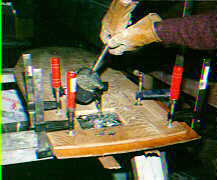
leadmeltleadpour

Melting, and pouring the lead.

George Cobb’s hull nears completion

George Cobb, of New Brunswick, Canada, sent me a bunch of photos of his beautifully crafted lapstrake Chebacco-20 hull. George writes:

I enclose photos going back to March ’97. I started Aug ’96 but spent most of that winter on spars, CB & trunk, rudder etc. working in the basement. As you can see from the photos, my shed doesn’t have enough room to build a boat of this size. Most of the construction went smoothly. Some trouble lining off the lap lines becuase I didn’t have room enough to stand back and look at them.

In the latest photos I am in the process of applying epoxy & the fiberglass to the deck. I have just started on the cabin. I laminated a rounded front as I did not care for the pointed look in the plans. I made very few other changes to the plans. Still have cockpit coaming, cockpit sole, toerails and rubrails and various trim pieces. All hatch covers are made except for the one for the companionway. When finishing and trailer are included I doubt if I will be launching this year.

cobb1

Starting planking – note the ‘lining off’ battens.

cobb2

The turnover ceremony.

cobb3

Starting to fit out the hull

cobb4

The cockpit nears completion

Ed Heins buys Burton Blaise’s hull

So I was pondering the next project, either a Light Scooner, a Chebacco, or one of the sets of Jim Michalak’s plans that are residing in my “projects pending” file, when lo and behold, Burton Blais posted an unbelievable deal for his Chebacco hull which made up my mind all at once and made me the newest builder on the Chebacco news list. The deal was even more attractive, as Burton, up in Ontario, is only a few hours northwest of us here in Frostbite Vermont. Burton, by the way has done a magnificent job thus far. That about covers the upside of the situation.

The downside? Well, convincing my wife Deb, was the next step. Of course it seems Deb, beautiful flower of English womanhood that she is, was somewhat less than overwhelmed at the marvelous opportunity of having yet another “bloody ship” in her back garden. Fortunately, the age old solution of providing a “quid pro quo” of greater value than the object in question, (this time in the form of a tennis bracelet) worked to perfection and the necessary political groundwork had been laid. Which then left only the logistic issues to be solved.

Downside #2, we had no trailer to transport this beast. After a caucus with Bill Samson about trailer requirements, however, I petitioned a friend to loan me the trailer from his 15′ plastic puffin which theoretically just got me enough snubber to axle length to balance the Chebacco. One small problem it seemed however was that like most Vermonters, maintenance on said trailer had been sadly neglected, so before embarking I had already rewired the lights, changed out one wheel bearing and being a Vermonter myself felt that I could get by with just repacking the other 3. Mind you I had never seen a Chebacco up close and personal, so I’m envisioning at this stage, how this is going to fit.

The morning of May 16 broke sunny and warm, a lovely day for the drive. We headed west across Vermont, caught the lake Champlain ferry just north of Burlington VT and landed safely in Plattsburg, New York. From there we headed northwest up route 190 and transitioned to US 11 at Ellenburg Depot. We left US 11 at Malone NY ( a rather niceish town with a hellatiously big Kmart, best described as a Tescoish thing for our British readers). Anyway the significance of the Kmart is that there are none in our small locale so it was planned to stop on the way back

to satisfy her majesty’s shopping fix. US 37 leaves Malone and runs west along the Canadian border to where we planned to make the border crossing. All was well here until we discovered 25 miles of roadworks with no feasible means of avoidance. Hence, 25 miles of dust and gravel later we were back on rt 37 heading towards Massena New York.

Now, Cornwall Ontario is a small city. At least on the map it looks substantial enough to warrant a signpost on the freeway. However… as with our US mapmakers who show Canada as a big beige empty block above the US border, I suppose the powers-that-be assume that just a reference to “Canada” should be sufficient for the average ignorant yank motorist. Therefore, the only signpost along the road reads “Industrial Plants Bridge to Canada”. Now it seemed absolutely logical to me to think this meant “THE Industrial Plant’s bridge to Canada”. There was an enormous factory there, and it’s not unheard of to have a factory in these parts span the border. (That’s my story and I’m sticking to it) Anyway, needless to say, 6 miles farther down the road we came to the realization that in fact this was the ONLY bridge to Canada. A clandestine U turn with a trailer across one of those “Emergency Vehicles Only”

median crossings and we were headed to Ontario.

Border crossing south to north was no big deal. The Canadian folks were friendly courteous and checked Molly the Bassett Hound’s rabies papers, and passed us right through. Burton God bless him had given excellent directions so the remaining miles were insignificant.

Until we arrived at the Blais’ estate and I got a look at the Chebacco, upside down on it’s building frame, and was appraised of the size of a completed Chebacco Hull. I would have sworn that it would never fit on the dinky trailer hitched to my minivan. Not wanting to admit defeat however, we pressed on and horsed the hull out of the temporary shed. With the help of a willing neighbor turned it was over for the first time. I have the feeling that if Burton had turned this over prior to my arrival, I probably wouldn’t have gotten a chance at the boat.

This was one pretty hull all trued up with the bulkheads and temp frames still inside. But onward….

Downside #3, Back to the Vermonters lack of trailer maintenance. It seems the trip had broken loose a couple of ancient weld patches and there was no way the trailer would have survived an overload condition in that condition. Thankfully another of Burton’s neighbors came to the rescue with a grinder and welding rig, and an hour later we were back in business.

Back to Burton’s, to load up the hull. Cripes it overhangs. Well at least the bunks fit more or less on the flat bottom although they’re somewhat short for the job. A bit of gerryrigging got her sorted and tied down & we were off back south.

Actually it trailed not too bad. There was a minor skirmish with the US customs who first after inquiring about my 2 children in back, (one boy, one dog, OK that put me off) then their obvious struggle with how they were going to get a Coast Guard safety registration certificate on an unfinished hull. (I’d love to see the exam for customs agent) Finally they acquiesced to the fact that this was really lumber at this stage so there wouldn’t be duty.

We made the obligatory stop at Kmart as promised, spent the night in Ellenburg Depot and returned uneventfully with only a few scratches in the paint to show for the ordeal.

This weekend, marks the building of a proper cradle and 8 strongbacks to horse the hull off the trailer and hopefully embarcation of further boat building exploits. Stay tuned. I’m a little overwhelmed at where to begin.

Cheers

Ed Heins

For Sale

I want you fellow Bolgerphiles to be the first to know that Catfish Lounge [a Catfish Beachcruiser] is going to be offered for sail, er, sale, to make way for a Martha Jane. Price of the Lounge is $4,500, and includes an excellent Pacific galvanized trailer and a year-old Honda 2HP motor. If you have an interest, or are interested in learning more about the boat, send me e-mail. (Both the boat and I are in the San Francisco Bay area.)

John Tuma <jtuma@sjm.infi.net>

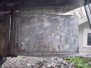
What about an aluminium rudder?

Fraser Howell sent me this photo of his aluminium rudder. He is very pleased with the way it works. It’s very strong, too. It’s worth noticing that the rudder is in a particularly vulnerable position when a Chebacco is being launched from a trailer. Careless launching can mean the rudder hits the slip when the boat slides off the trailer. It is comforting to have a really strong rudder!

frudder

Fraser Howell’s aluminium rudder

And finally:

That just about wraps it up for this time. Please, please, please keep your news and photos coming. They are the stuff that Chebacco News is made of!

Bill Samson,

88 Grove Road,

West Ferry,

Dundee, DD5 1LB,

Scotland.

<wbs@sol.co.uk>

Chebacco News 20

Chebacco News

Number 20, March 1998


SYLVESTER makes an overnight trip

We don’t get much news about trips in Chebaccos, so here’s an account of one I did on 5th August 1997. It’s based on notes from SYLVESTER’s log (Yes! I keep a log of all my trips – Is that sad or what?). Low water was due at 11 am, so I got down to the shore at 10, rowed TWEETIE-PIE (my June Bug) out to SYLVESTER and got her ready.

lei0016

SYLVESTER at her (his?) mooring

I was underway, single-handed, in a force 3 Easterly, at slack water at 10-30 am.

The Tay is a rather shallow estuary, with loads of sandbanks and very few buoys to show you where they are, upriver of Dundee.

lei0013

Heading upriver, towards the Tay Road Bridge.

It was my intention to get upriver to the Earn – which enters the Tay from the South, just West of Newburgh – and to motor up there to Bridge-of Earn. But . . .

estuary

The route taken by SYLVESTER (The total extent of this map is about 25 miles E-W)

You’ll just be able to see, on the map above, that there are two bridges across the Tay. The Easternmost is a road bridge, and the other is a rail bridge. I had a pleasant run upriver until I passed under the rail bridge. Just beyond the bridge I ran aground on a sandbank, but the flooding tide soon lifted me off again.

taybridg

Just about to pass under the Tay Rail Bridge

From then on, I paid close attention to my charts, and avoided the sandbanks, most of which are on the North side of the river. The banks are complicated around Newburgh, but there are some pint-sized buoys to allow boats to thread their way among them. The locals amuse themselves on a nice afternoon by watching yachtsmen come to grief – often having to spend the night on a bank!

towing

TWEETY-PIE (a June Bug) towing astern – Tay Rail Bridge in the background.

The mouth of the Earn is not far beyond Newburgh, and I headed for it. Unfortuately, no-one had warned me that you need to keep well out in mid-stream before turning up the Earn, so, once again, I ran aground. By this time, the wind was gusting force 4 or 5 and things got a bit fraught. Even though the tide was flooding, I kept getting blown higher up the bank. I dropped the sails and started the outboard, hoping to motor off the bank. Unfortunately, the propellor had an argument with some rocks and the shear-pin broke.

My only option, now, was to continue sailing – The Earn is too twisty and narrow to sail up, so I decided to continue up the Tay. I eventually managed to pole myself off the bank and made my way under main alone up to Inchyra, where there are some moorings on the North side of the river, belonging to the Civil Service Sailing Club.

inchyra1

At anchor – Inchyra.

I dropped my hook (a 15 pound Danforth), replaced the broken shear-pin and rowed ashore. I had brought the June Bug with me, under tow. Two of the Civil Service guys were there and made me very welcome with a mug of coffee. They also pointed out a spare, permanent mooring that I could tie up to for the night, and save me the trouble of anchor-watching when the tide turned.

Having moved to the mooring, I rowed ashore again, tied TWEETY-PIE to the jetty and walked the mile and a half to the nearest pub, the Glencarse Hotel, for a pint and a sandwich. I got back to the jetty a couple of hours later, about 9pm, and found TWEETY-PIE dangling by her painter down the side of the jetty – It was approaching low water again! A hot drink, contemplate the sunset, then off to bed.

inchyra2

Sunset at Inchyra

Next morning, I got up at 5am, had breakfast, and set out at high water – 6am. There was no wind, so I motored back all the way, dodging the sandbanks, and got home at 9.30.

Verdict? I don’t think I could have been happier with any boat, than I was with SYLVESTER (and, of course, TWEETY-PIE).

More about Reefing systems – a two-way conversation

Following Brad Story’s account of the reefing system he uses on his Chebacco, Bob Branch got back to me with some suggestions of his own. This led to a two-way discussion of possibilities that may be of interest to Chebacco-riggers.

Bob wrote:

Thanks for issue #19. Another good job as always.

That was a nice pic of the “c” under construction under the lean too. [Jamie Orr’s hull]

A suggestion on the reefing system Brad demonstrated. Works nice but those

cleats on the boom can be a problem when reefing… trying to find them on a

flailing boom, stuck under the sail cloth, and you head having to be in such

close proximity to the boom (a bad idea in heavy weather in any boat from my

experience.) The reefing system I have used on a number of offshore boats is

just a mod of the one Brad sent. It brings the topping lift and the clew reef

lines to the mast and then turns them to the cabin top to cleats on the aft

end of the cabin. I know it adds the cost of a few blocks and sounds like a

bit of spigetti. But I have routinely used 3 reefs, topping lift, boom vang,

and in sloops all the jib and spinnaker halyards (though I reversed my

thoughts on those if much single handing is done without roller furling {never

roller reefing} on the headsail. It gets the crew out of the cockpit (where

its weight ought not to be) and puts the jib halyard at a more convenient

location for a controled sail takedown for the solo sailor). Anyway, it can

all be done very neatly. When you are reefing with this arrangement you are

not AT ALL dependent on control of the boom. In fact I get it the heck out of

the boat completely. I take up tension on the topping lift first so the boom

will not drop AT ALL during the reef. I ease the main sheet way off till the

boom is out of the cockpit completely (and away from my precious skull). Then

I lower the halyard and secure the tack (take in the tack reef line) tightly.

The main halyard is tensioned… very tight so the draft in the sail winds up

in the forward part of the sail when the sail is set. This is critical for

pointing upwind in a cat rig. The clew reef is then taken in and tensioned to

the max. You need this tight to really get a flat sail which is what you are

looking for just as much as sail area reduction. Now I haul the mainsheet and

away we go. Note, I didn’t do anything about the excess sail cloth. Right. If

the outhaul was tight to start with (which it should have been because you

were already at upper wind range prior to the reef) and the reef outhaul is

tight (which it should be) The excess cloth will be in a fold or two very

tightly against the boom. Even with a second deep reef in a high aspect main I

have NEVER found it necisary to tie the excess cloth. If the boom doesn’t have

adequate cockpit clearance or cabin top clearance to keep the sail cloth clear

you might have to but now the boat is back under control, the boom is under

control and not swinging around, and it is a simple matter of two ties at most

for the entire sail. The boat isn’t pitching anymore either! And ya never left

the cockpit. One little detail. When you make your sail or order it from the

sailmaker, be sure the reef clews are a little higer than just a perpendicular

from the mast. You want more angle upwards for the boom when you reef… so

the cloth has the room it needs, and so your precious skull is further from it

too.

I now it won’t happen in a Chebacco, but true luxury in sailing is NOT to be

found below decks. It is a boat whose boom is always above your head, during

normal sailing, tacking, jibing, and when reefed. Ahhhhhh. Peace of mind.

Keep the scratched side down, (your shallow draft Chebacco does have a scratch

I hope… otherwise you aren’t in the water it was designed for.),

BOB BRANCH

I replied:

Dear Bob,

Many thanks for your sensible suggestions re: reefing. It wouldn’t be practical in my Chebacco as it stands, because there is no gooseneck to hold the inboard end of the boom at a fixed height – something that I think’d be essential when a line comes off the inboard end of the boom to a block at the mast-foot. Otherwise the halyard tension would be working against the reefing line tension with potential mixups if one or other is slackened off. My Chebacco boom has jaws at the mast end and no tack downhaul – the weight of the boom is enough to flatten the sail. The trick is to balance the tensions in the throat and peak halyards.

Having this setup, I can raise or lower the entire sail/spars. I normally keep the boom above head-height. The only discomfort that can befall the crew is being throttled by the mainsheet in a gybe!

Yes, I do have a few honourable scratches on the bottom of SYLVESTER. Fewer than I’d expected given the horrible grinding noises when I ran aground last season. I have a galvanised steel strip around the keel which bears the brunt of such navigational misjudgements!

I’ll put your thoughts into CN#20 – some of the guys do use goosenecks and could benefit directly by adopting the system you suggest.

Bill

Rudder Issues

Burton Blaise emailed me regarding some concerns he has about the Chebacco’s rudder. My reply is printed below. His words are in italics –

Hi Bill:

Hope things are well with you. I am back at my workbench trying to do whatever I can on my Chebacco project in my small heated workshop. I am contemplating building the rudder so that it is ready to be attached to the hull in Spring. Looking at the plans, it strikes me how small the rudder appears – not much more than 1.5 square ft total area – and I wonder how such a small rudder can effectively steer such a (relatively) large boat. After all, the rudder blade for my Gypsy (which is a much smaller & lighter boat than Chebacco) is significantly larger. In your experience, how well does Chebacco respond to her helm? I worry that the rudder as shown might make for poor steering ability!! I realize that this design does have a bottom plate for extra “bite” when heeled, but I still worry that the rudder surface is much too small for a boat of this size.

I worried about the same thing when I was building, but Brad Story reassured me that it wasn’t a problem. He was right. The only anxious moments I’ve had were immediately after letting go of my mooring, before SYLVESTER had gathered much way, trying to steer the boat before being swept against the other moored boats by the tide. Mind you, the sail and CB have as much to do with steering as the rudder, and I haven’t had any problems since I got used to that aspect. I suppose that if the boat heeled a great deal, the rudder might come clear of the water – again something I’ve never experienced. I understand that some boats with much larger rudders are tricky to steer – Peter Bevan tells me that the Light Schooner won’t respond to the rudder unless the sails and CB are set just right.

You need to pay close attention to the steering when surfing downwind, but that’s the case with any boat. I’ve never felt in danger of losing control.

I also have a question concerning the pintle and support structure for the entire rudder and its post. From what I gather from the plans, the entire weight of the rudder assembly is borne on the pintle, with main support for the rudder post where it comes through the mizzen mast partner (which is strengthened with a small steel plate where the post comes through) – is this correct? If so, what stops the rudder from riding up and down, and possibly scraping against the bottom of the hull (especially in wave action?)? Should there be some kind of stop on the rudder post to prevent this action, or does this simply not happen at all?

Yes, it does ride up and down. Mine has about 1/2″ of vertical play. There’s no sign of significant wear, though it is a little looser now where it passes through the mizzen partner. I’m sure that this is as much to do with side-to-side movement as up and down, when sitting on her mooring. As a matter of interest, I’ve put a thick nylon washer around the pintle to take the wear and reduce friction.

Also, the plans appear to show a free flooding rudder, but I really wonder if this is necessary. Surely weight cannot be an issue here, since the space between the two plywood rudder cheeks has such a small volume as to be almost negligible.

Sure. But the main idea is to let water out. There’s always a danger of water getting trapped in any hollow structure, no matter how well sealed it is. I regard these as drain holes.

Also, if I use steel for the rudder post assembly, what is the best way to keep the lot from rusting? I had considered aluminum or stainless steel for the job, but I simply do not have access to the proper welding equipment, etc.. How did you handle this?

I got mine welded up from mild steel, then sent it off for hot dip galvanizing. I got a blacksmith to do the fabrication of the rudder stock and pintle and it cost me 25 pounds. The galvanising was another ten. So far, it’s held up well. When it rusts significantly I’ll take it all apart and send it off for re-galvanizing.

Bill

More on Rudders

Jamie Orr writes:

I’ve found a “retired” machinist to make up the rudder fittings in stainless steel. I wanted to use bronze where I could, but was told by at least two outfits that bronze was best cast, not welded/brazed. Also the flat stock is hard to obtain. So, since casting a single set of fittings is a bit expensive, I’ve yielded to the experts and plumped for the stainless. The lower rudder fitting is made out of 1/8th stock,

bent up around the skeg, with lower sides at the back part as well to add strength, making a 3/4 “cup” around the bearing. This fitting is already bent and welded to shape, but hasn’t got its pin or any holes drilled yet. The rudder post will be 1+ 5/16 stailess tubing, a bit thinner than called for, so I’ll have to fair in the rudder to the post. I’m having the straps welded on as if the rudder is only 1+ 5/16 as well, to get a longer weld — that is, a full 180 degrees on the post. I’ll cut down the rudder to fit in way of the straps — should be strong enough with the framing backing it up.

My machinist is also making nylon bearing/bushings for the bottom and at the tiller. The lower one will be wider at the bottom for the post to sit on, with the upper part fitting inside the rudder stock, and the pin hole drilled up through the nylon. The top one will be a bearing as well as pad out the width of the rudder stock to match the tiller width – stainless again for the rudder straps.

I’m trying to decide how high tech to go in paint, and whether to bother with bottom paint on a mostly trailered boat (probably not). I don’t want to go the length of a two part polyurethane, despite the finish, but I am considering the one part “Brightsides” mentioned in the Bolgerlist from time to time. I’m also very tempted just to go with a

good quality enamel, on the grounds that I won’t have to learn any new painting techniques or take up chemistry.

Jamie

And finally . . .

That’s all we’ve space for this time. I hope you enjoyed it. Keep your letters and emails coming!

Bill Samson,

88 Grove Road,

West Ferry,

Dundee, DD5 1LB,

Scotland.

Chebacco News 19

Chebacco News

Number 19, January 1998

Is Electric Outboard Power feasible for a Chebacco?

Gil Fitzhugh wrote to Phil Bolger and Friends –

Dear PCB&F,

. . .

I’ve been intrigued by ‘Lily’ [the electric launch] and saw her or a sister ship at St Michael’s last month. I’m not looking to build or own a power boat, but I’d welcome your views about whether the newest electric outboards with a modest number of batteries would provide reasonable auxiliary power for a Chebacco. I shouldn’t think I’d need to motor more than 3 hours between charges – usually less, since I wouldn’t go anywhere far in a Chebacco if I couldn’t anticipate reasonable sailing – and maybe a couple of solar panels on the cabin roof (or deck house) would replace, during a day’s sail, what I’d used up motoring out of harbor in the morning. Otherwise, I figure a 5-horse Honda 4-stroke would be the next-most environmentally friendly source of adequate power. Thoughts?

Best regards,

Gil Fitzhugh

PCB&F replied –

Dear Gil,

. . .

On your E-power idea, the matter is straightforward and viable for the milder duty cycle you propose if you take it seriously. Before LILY, we hung two smaller 42lbs thrust MINNKOTAs on Ted Ratcliff’s 20′ ply Chebacco ‘KATTEPUS’ and she went quite well, only hampered by the limited pitch (one size only available) on the props.

The following hardware should be good for up to 5 hours of continuously powering your boat:

  • 65/70lbs thrust 24 volt MINNKOTA (saltwater series optional for coastal use) [$430],
  • 4x6V TROJAN T-105 for 217Ah (or T-145 for added range and cost!) [4x$49 or $129] connected in series to get 24V, but interruptable by
  • single battery switch into two banks of 12V [$20], which in turn can then be charged readily in less than overnight by a
  • 40Amp STATPOWER 4-stage ‘smart’ charger with two-bank output to feed each 6V T-105 pair with 20Amps as de facto one battery [$350]
  • You could add an E-meter [$160] to gauge consumption and get instant reading on voltage and actual amp and amp/hr numbers – useful and instructive.

This will cost more than any combustion engine. But after initial installation, and very minor battery maintenance you’ll be running her for years without additional worry, never mind noise, vibration or oil-plumes – decent return for the money. E-cost will be on the order of perhaps 80c-$1 per total charging cycle . . . But always recharge immediately after you bring her back within reach of the nearest 110V outlet.

Put two batteries in about the location in each cockpit bench where [the Cruising Chebacco] plans show a single one. And locate the expensive charger inside the cuddy/house to keep it out of the rain. LILY’s rain-proof units would take twice as long to recharge these 6V pairs, and seem thus way too wimpy for the occasion. Your E-CHEBACCO would have about 2/3 the capacity of LILY. You probably won’t see more than 4Kt due to the limited pitch on that 11″x4″ prop.

. . .

Susanne Altenburger

Phil Bolger

Hanging the bilge planks on a Sheet Ply Chebacco:

Skip Pahl has been comparing notes with Jamie Orr regarding the hanging of bilge planks. He kindly copied this email to me:

Dear Jamie,

Thanks for all the good information in CN about your building methods and

experiences. Your advice is really timely for after several years of

deliberations, courage and model building, I began cutting wood this summer.

Progress is slow. My building speed is limited by the ability to buy only

three sheets of plywood (or its $ equivalent) every two weeks! Add to this

the fact that I’m very slow when it comes to new types of construction and

you’ll understand why I am straining for new wisecracks to answer the

inevitable question, “So, when’s the big launch date?”

I am writing to you because it is approaching the time to hang the bilge

planks and I am struggling to visualize the process. I too wish to avoid

building all that stress into the hull that 1/2″ ply creates when making that

“Gawdawful” twist and have decided to go with the 1/4″ ply laminations.

I made 7:1 scarf joints when I layed-up the 1/2″ sheer strakes and bottom.

They worked out really well. The curves are fair and the joints appear to be

very strong. However, with laminated bilge strakes it looks as though the

butt block is the way to go. Would you review my thinking here and see if

I’ve got the process right?

PART 1 ( (No volunteers required)

1) Trace mylar or craft paper templates on bilge openings on each side.

2) Transfer template shapes onto for bottom layer plywood. Cut out and

coat outboard surfaces with rolled layer of unthickened epoxy. Allow to cure

and sand.

3) Make 4″(?) wide butt blocks out of 1/4″ plywood and attach to aft end

of each of the forward sections of the bilge strakes. Use thickened epoxy and

bronze screws to clamp.

4) Attach forward section of each strake to the stem using bronze screws

only and begin working aft making temporary clamp blocks that are attached to

the shear strake and bottom. Use wire stitches as needed to fair.

5) Attach aft end blocks to middle sections of bilge strakes.

6) Hang middle sections of bilge strakes by beginning at the forward end

butts and working aft. Use bronze screws and epoxy at the joints with wire

stitches at the top and bottom to keep joints fair. Work aft using wire

stitches and clamp blocks (no glue).

7) Hang aft sections of bilge strakes using bronze screws on transom.

8) Go back and unscrew planks at stem and transom and reattach with

epoxy and epoxy/cabosil putty.

PART 2 (Volunteer required)

1) Transfer template shapes onto top layer of unjoined plywood and cut

out.

2) Pre-drill an 8″ grid of holes in exterior panels to allow for escape

of air pockets in laminating.

3) Masking tape interior seams closed so epoxy will not run into

interior of hull.

4) Dry fit exterior lamination panels and mark for future positioning.

5) Beginning with the center panel, roll thickened epoxy onto outboard

surface of inside lamination and unthickened expoy onto inboard surface of

exterior lamination.

6) Join the two panels with pan headed screws beginning at the center

and working forward and aft.

7) Apply forward and aft sections of exterior lamination in similar way

using bronze screws along the butted seams. No butt blocks are used on these

seams inside the hull.

8) Before epoxy has cured, apply unthickened epoxy to seams and follow

with epoxy/cabosil putty mixture to fair.

Sorry this took so long. Please let me know if I’ve got it screwed up. I

have nightmares of things getting stuck together crooked.

Thanks for your help.

Skip Pahl

These sound like sensible procedures. My only comment is that I’d probably thicken the epoxy, a little, between the laminations – but that’s just personal prejudice.

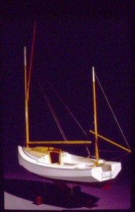
Skip also sent this photo of a gorgeous model he’s built of a sheet ply Chebacco:

transom

Skip Pahl’s model of a Chebacco-20

Uncured epoxy

Just about every boatbuilder will at some time in their career experience the horrors of uncured epoxy. This happened to Burton Blaise, who sent this nessage out to a few of us. In short, getting it off is not a lot of fun:

In case anybody is interested in my continuing epoxy saga, I am

pleased to report that, after a gruelling week-end of scraping, grinding

and sanding, I finally got all of the gummy epoxy off my Chebacco hull

and am back at where I was a couple of weeks ago (that is, ready to

complete glassing the hull – weather permitting!). As mentioned in an

earlier message, I found that the straight edge of a piece of broken glass

really works best to scrape the majority of the goo off. Any remaining

residue was removed using a belt sander fitted with a very coarse

sanding paper (30 or 40 grit). Anyone attempting the broken glass trick

should bear in mind the need to be EXTREMELY careful during the

scraping operation – I got carried away and careless, with the result that

my glass scraper broke in mid-stride, causing my hand to slip past the

glass edge and slicing a good way into my right index finger (after

bandaging my finger – which probably really should have gotten stitches

– I wisely resorted to completing the operation wearing thick canvas

gloves). This hull hasn’t even been launched yet, and already its been

baptized with my sweat, my tears (of frustration) and now my blood!

However, the way things are shaping up, I know that she’ll be worth it all

in the end. Yep, she sure is a shapely hull.

Burton

I’m certainly glad to hear it worked out OK eventually!

Chebacco too big for you? – Try a ‘Bobcat’!

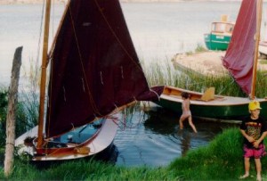
Colin Hunt of Australia sent me this photo of a pair of Bolger ‘Bobcats’ (a.k.a. ‘The Instant Catboat’, ‘Tiny Cat’, ‘Little Gaffer’ . . .). Colin points out that the construction of the 12 foot hull is very like that of a sheet-ply Chebacco hull. They are excellent daysailers and family dinghies, too. So – if you’ve not quite decided that you’re ready to take on the construction of a Chebacco-20, why not hone your skills by building a ‘Bobcat’? Plans are available through PCB&F, as well as Dynamite Payson, who has also published the excellent ‘Build the Instant Catboat’, which is an almost indispensible aid to construction.

ch171

A pair of ‘Bobcats’ by Colin Hunt.

Reefing systems for a Chebacco

I was recently caught out in a force 5, under way, single handed, and had the uncomfortable job of trying to put a couple of reefs in while slithering around on the cabin top, avoiding being swept overboard by the flailing boom. It’s no secret that the Chebacco is fairly tippy, initially, (though with superb secondary stability) and so whatever side you approach from, the boat heels in that direction and the swinging boom heads your way! I eventually backed the mizzen a little so that she hove-to on port tack and thus was able to approach the boom from the starboard side, where the cleats for the reefing pendants are attached.

Although I got her well enough reefed to sail the 7 miles back to my mooring, the sail was a tad baggier than I thought ideal, and I felt there must be an easier way to do things. So I phoned Brad Story, who has built and sailed more Chebaccos than anyone else. He suggested that I would have been better to lower the boom into the cockpit, or into a boom crutch to hold it steady while I was working on the reefing. Seems obvious now; I wish I’d thought of it! Secondly, the cleats for the reefing pendants should be positioned so that they can be reached from the cockpit. Good thinking!

Brad writes:

Dear Bill,

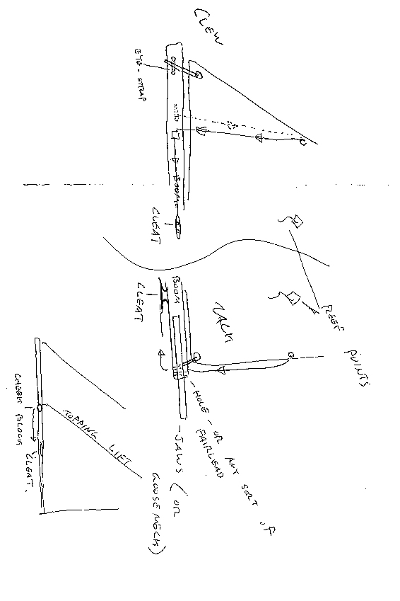
I’ve tried to sketch some details of my own rig. The topping lift is on one side only (keeps it simple!). At the mast head is a loop spliced into the topping lift. It’s held up there with an eye-strap or two. From there it just runs to a cheek block on the boom, and then forward to s small cleat. It’s very handy – it’s right in the cockpit. It can never fall down and it’s one less line to deal with when setting up or striking the rig.

The jiffy reefing lines I’ve sketched, also. At the tack, a single line is made fast at the upper grommet. It runs down the luff, through a fairlead (hole, whatever) and aft to a cleat on the bottom of the boom, far enough aft to be reached conveniently. At the clew, a line is made fast to an eye-strap on one side of the boom (below the appropriate grommet and alittle bit aft). This line runs up to the grommet , through it and back down to a fairlead (or small cheekblock) and forward to a cleat. When it’s time to reef, just lower the sail a bit, haul both of these lines until the grommets are where they should be, and cleat them off.Now all you need to do is bundle up the foot of the sail. Again, it’s fast and convenient.

Brad Story

brad

Brad Story’s sketches of reefing arrangements

Jamie Orr’s hull nears completion:

Jamie Orr of Victoria BC, Canada, sent me this picture of his hull. He reports that he’ll be making the sails over the winter, when it’s too cold for epoxy work. He’s using 5.4 ounce cloth and plans to make a jib, as well as main and mizzen.

SORRY – THIS PHOTO HAS BEEN LOST

Jamie Orr’s sheet-ply hull

And finally . . .

That’s all for this issue. Here are some addresses that may be of interest to readers:

Phil Bolger & Friends, PO Box 1209, 29 Ferry Street, Gloucester, MA01930, USA (- Designers of the Chebacco boats and source of plans for all versions)

Harold H Payson, Pleasant Beach Road, South Thomaston, ME 04858, USA ( – Author of ‘Build the Instant Catboat’ and alternative source of some Bolger designs)

Brad Story, Boatbuilder, Box 231, Essex, MA 01929, USA (- Originally commissioned Phil Bolger to design the Chebacco boats, and has built many superb examples of them)

Bill Samson, 88 Grove Road, West Ferry, Dundee, DD5 1LB, Scotland ( – Editor of Chebacco News)