Hello Richard:
I want first to thank you for continuing Bill Samson’s work in editing the Chebacco News. I have learned a great deal from this newsletter and appreciate very much Bill’s work on behalf of Chebacco builders.
In his very helpful description of the building sequence for the sheet-ply Chebacco 20, Bill describes how he installed the two hull side panels by suspending them from the ceiling while he fitted them. Since I am building outdoors and do not have a ceiling, I had to find another solution.
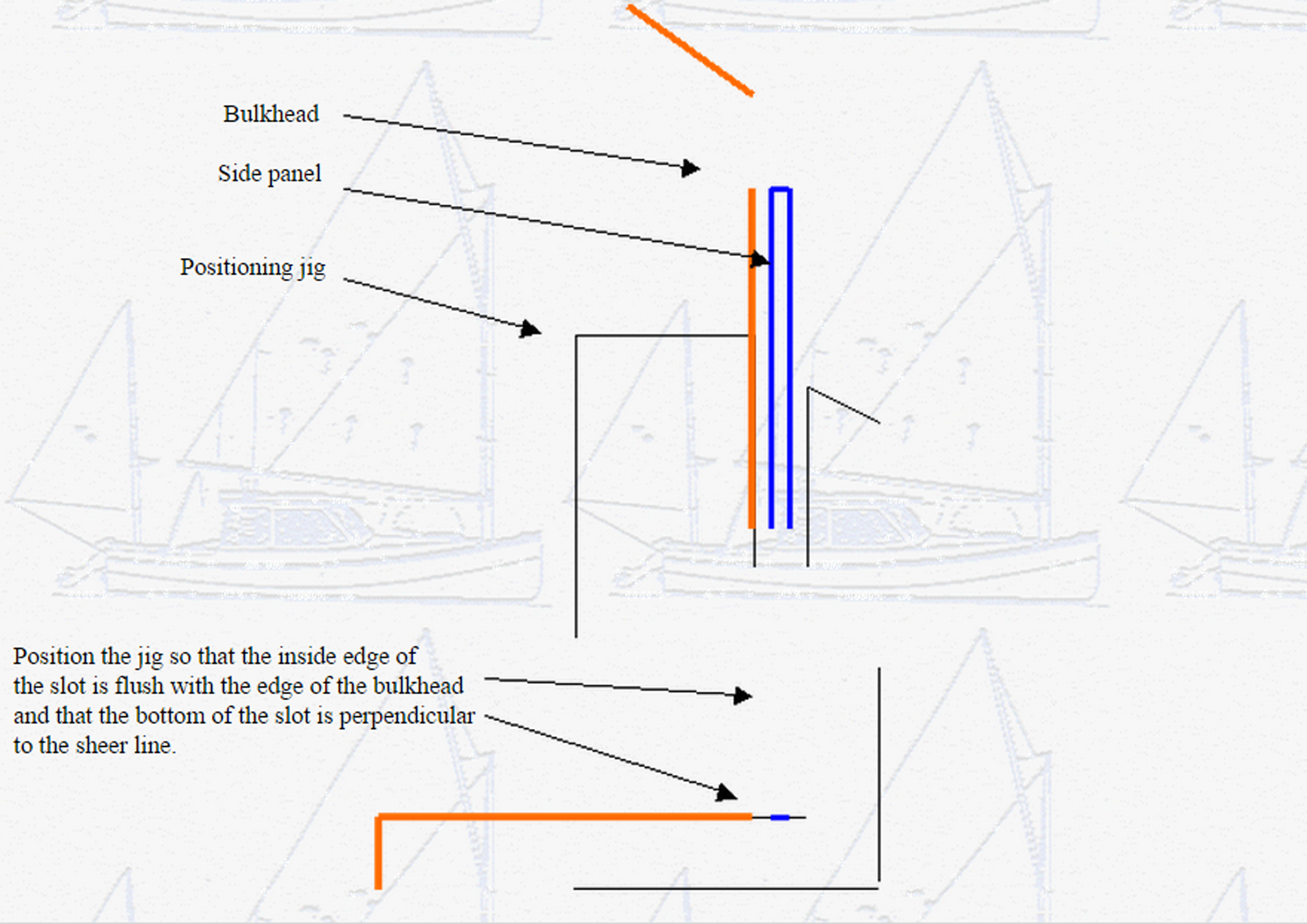
My approach, therefore, was to cut out six small jigs out of scrap plywood (I actually used the cutouts from the bulkheads.). These were screwed temporarily to bulkheads # 1, # 4, and # 6 as shown in the diagram below. The side panels were then dropped into the slots, three on each side, and I was able to take my time in positioning the panels. When the epoxy fillets were complete on one side of the bulkhead and the panels were permanently fastened at bow and stern ends, I removed the jigs and made the fillets on the other side of each bulkhead.
I found this to have been very easy and I hope that it might be of use to others as well.
Regards, Tom McIllwraith
Halifax, Nova Scotia
***
Hi Richard,
Thanks for the nice job on the last issue of chebacco.
Here are the pictures of blocks and tabernacle fitting
that you requested.
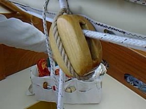
on a 5 mm brass pin (Fig. Block1.jpg). They run nice and smooth
as long as the hole in the sheave is a bit larger (e.g. 5.25 mm)
than the pin. As I mentioned before, I made patterns
by magnifying the drawings in the “Riggers apprentice”
by Brion Toss. I also fitted the block on the centerboard
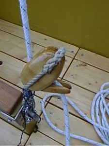
case with some kind of slotted tongue (Fig. Block2.jpg)
to jam the sheet, a home-made simple substitute for a camcleat.
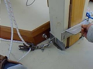
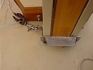
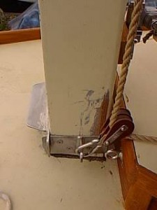
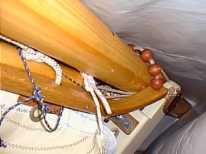
The stainless steel fitting for the tabernacle was “invented” and made by
my friend Roberto Ginetto. There is a U-shaped part that goes around
the back and sides of the tabernacle. This part is screwed onto the tabernacle.
The front part is removable (Fig. taber1.jpg) and goes on the u-shaped part
like a “fence”. The U-shaped part also has “ears” (Fig. taber2.jpg) to attach
the double turning blocks for the throat and peak haliards (starboard side,
Fig. taber1.jpg) and topping lift + jib haliard (port side, Fig. taber3.jpg).
As you can see, things are still a bit scratched and unfinished around there
but the whole thing works well and is very easy get on and off single-handed.
Let me know if you need more explanation or other info.
Cheers,
Vincenzo
Do you have any close up pictures of the hinge on your tabernacle?
Also, I notice you have the forward section closed off. What is the distance from the hing to you locking mechanism?
How do you raise the mast? You use the jib line as a forstay, do you use it to hoist the mast?
It appears your mast is rounded up top, but square on the bottom. It is square up to the double reef position of the gaff?
Have any closeups of your gaff saddle?
Hi Richard,
It is very easy to raise the mast, I just stand on the cabin roof and walk it up, it takes only a second then to block it with the metal fence. I do not use the jib haliard as a forestay or to raise the mast, although I guess that could be done.
The mast must be rounded all the way above the hinge point, otherwise the gaff jaws will not be free to swing around when hoisting or lowering sail (acting as a wrench around a bolt) and might bust at the first gust of wind! So, the mast is left square only in the part that goes into the tabernacle.
I will take close-ups and measures over the weekend.
Buon vento,
Vincenzo.
Richard,
the distance from the pin of the hinge to the bottom of the locking mechanism is 67 cm.
The width of the steel plate of the locking mechanism is 6 cm.
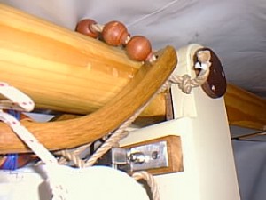
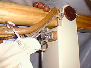
I made the curved gaff jaws epoxying 2mm oak lamination to a final thickness of 24 mm
(see attached pictures)
Cheers,
Vincenzo
Did you use the 1 inch stainless steel rod described in Chebacco News 18 for the pivot pin?
I’m thinking of going a little thinner, to have less of a hole in the mast.
Did you do any kind of reinforcement for the hole in the mast?
The round plate with the three screws, this is the bearing plate for the pivot pin? Are all the mast forces taken by this plate, or is it a loose enough fit that the mast forces are taken by the box section of the tabernacle?
PCB&F says: “Since we know of no widely available source for them any more, we are proposing a ‘home-made’ gooseneck. It uses two stock ‘heavy duty’ SS gudgeons to accept a 1/2″ SS eyebolt which then connects via another ‘undersized’ bolt loosely to two SS tangs that are screwed to the forward sides of the boom; there should be enough freedom for the boom to move any which way, including twist from the sheet-pull. ”
I was never sure what exactly they were saying. It looks like you have a 10 inch or so long, 1/2″ thick rod between the upper and lower brackets (gudgeons?) on the tabernacle face. I can’t see, but I’m assuming you then have an oversized eyebolt that slides up and down over this rod, is attached to the front of the boom, and acts as your gooseneck?
I used 1 inch bronze rod for the pivot pin.
To avoid having the pin bearing directly on wood, I screwed steel plates
(with a 1 inch hole for the pin), one screwed to the side of the mast, the
other to the side of the tabernacle, so the forces on the pin should mostly bear on the steel plates. The plates you see in the pics are just plywood plates that prevent the bronze pin from working its way out of the hole.
You are exactly right about my gooseneck. The pin is 12 X 30 mm stainless steel. I made it so long with the idea of rigging a downhaul to tension the luff. However the throat halyard is enough to give plenty of tension, and the sliding up and down of the boom is just a useless complication when hoisting or lowering the sail. I am going to cut that rod!
Pics of gooseneck details next weekend.
Vincenzo.
***
From: “Bill Samson” <bill.samson@tesco.net>
To: <richard@spellingbusiness.com>
Subject: New Chebacco growing on Vancouver Island . . .
Date: Sunday, November 11, 2001 2:41 AM
Hi Richard,
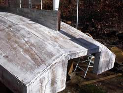
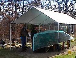
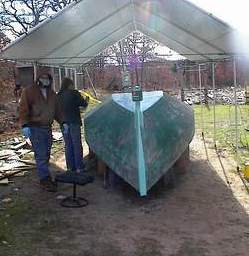
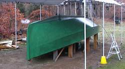
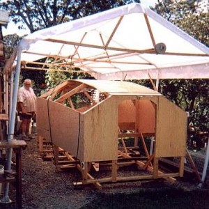
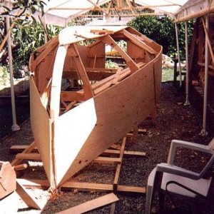
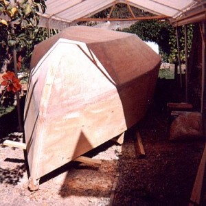
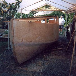
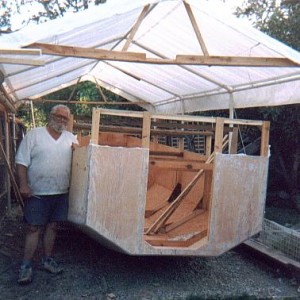
Just had these pics from Bill McKibben via Chuck Merrell of his ‘glasshouse’
Chebacco Motorsailer that’s coming along well.
Bill has raised the topsides a little more than is shown on the plans, but
(I think) kept the overall height the same. You remember the pic of his
model on one of my last Chebacco Newses?
Anyway, Bill would be delighted if you included one or two of his pics in
your next issue.
Cheers,
Bill Samson
>Speaking of pix, the attached just came in from B&B for the NW Chebacco.
>Will put them on his web page. They were taken in Aug and September. I
>have a hunch he’ll have it complete by sometime next summer. BTW, that
>green foliage, higher than the cover in Picture #1 is Beth’s corn crop from
>last summer. I had some they brought down. Delicious!
>Chuck
>
|
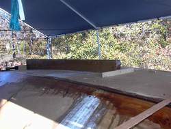
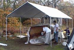
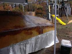
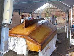
*** Hello Richard! A short note with 3 photos for your next Chebacco e-zine, the main purpose being to show how I’ve tried to build a Chebacco over the summer. As cold weather now comes over the Massachusetts hills here, I’ll soon be forced to close down boatbuilding work although I’m hopeful that an Indian Summer will come about to allow the finishing of the hull and flipping. Even in snow I’d flip her!
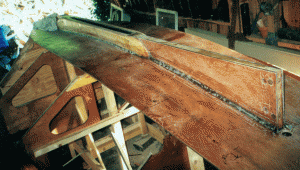
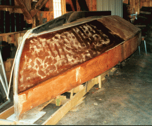
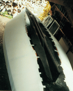
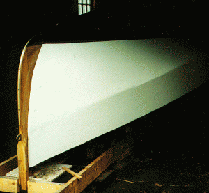
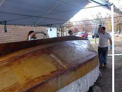
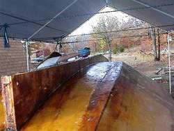
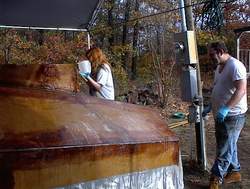
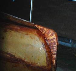
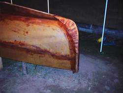
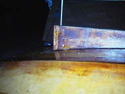
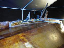
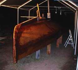
Photo 2 shows Stealing Horses with her bilge panels in place. The front 8 feet is composed of 2 layers of 1/4″ plywood with the first brought into shape with Spanish windlass action, and the second secured with a buttering of thickened epoxy and many sheetrock screws forcing the outer to the inner panel per Jamie Orr’s earlier description of how to do this. The aft sections of the bilgepanel are 1/2″. A brass half-oval strip extends over the inner stem, awaiting the outer stem for attachment. The strip along the forward keel, along both centerboard cheeks, down the aft keel but shy of where the rudder post attachment will be placed. Photo 3 shows the bilge and topside panels covered with xynole cloth prior to wetting out. The keel and most of the bottom has, as the photo shows, been cloth-clad and coated with epoxy laden with graphite. At this time — late October — the large xynole sheets have been wetted out and received 3 coats of fairing compound which cured just before the cool weather. Now the job of sanding the hull is sporadically underway. The outer stem–composed of built up planks of rosewood–has been lag-screwed and epoxied to the inner stem. The lagscrews are recessed into the inner stem and set in bedding compound. By the way, Jim Slakov (who built an exquisite lapstrake Chebacco) suggested to me one of his embellishments: that a small wood wedge be eventually epoxied to the inner stem to hold the mast at an intermediate stage when raised. The idea is to stand in the cockpit and raise the mast to this point (contingent on one’s height and muscle power), and then to leave it semi-raised and secured by the rachet effect of the wedge while climbing to the cuddy roof to complete the job. I’d like in what remains of this building season to get the hull sanded and the waterline scribed to the hull–I’d like of course to do more like paint and flip–but I’d settle for this. Soon I’ll be forced to unscrew the ladder strongback of the boat forms from the ground stakes that level it. The coming frost will of course heave these stakes and I’m concerned that the hull not be stressed so I’ll let it float atop frozen ground. Then an accurate waterline will be impossible. Semi-gloss marine enamel was bought for a 2-coat job above the waterline (to be placed about 2″ higher than the design waterline) with the graphite-laden epoxy coming up from the bottom. Kirby Paints was kind to test their various paints and primer on a sample of my plywood/my epoxy to see how to proceed (no primer was deemed necessary). For those considering a sheet plywood version of the Chebacco the following is a list of major materials and their sources that I’ve used: Cheers, keep warm, Dick Burnham Here is our Chebacco with 2 coats of oil-based Kirby semi-gloss white on her. The outer stem is as yet unfinished but we plan to sand it down and to varnish it.
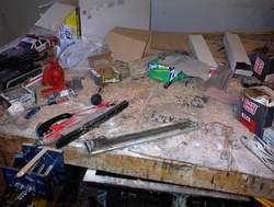
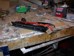
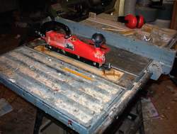
*** Hi Richard New email address – ‘rwheating@telus.net’ Apologies for not thanking you sooner for your work on the Chebacco News. I live in the same corner of the world as Jamie Orr. He lives on Vancouver Island and me on the main land. My Chebacco has been in the works since 1995 (!) I was searching for just the right boat project (my first) when I read the Chebacco article in the Wooden Boat magazine. However this would be a test of my dedication as my wife and I were just starting our family which I was to discover dramatically cuts into ones free time… Randy Wheating *** Sanding the CLCEveryone has been saying that this will be a cold winter. To which I have invariably replied “NO, it will be a mild winter, so I can finish the boat!”. And you know what? With the exception of a couple of days of snow, it has hardly gotten below 50 degrees yet… spooky. These are pictures my homemade power long board. To the left, I have just disassembled the inline air sander I bought from Harbor Freight. Center is where I have made up some small mounting blocks, and countersunk some 1/4″ flat head screws in it. To the right, I am gluing the blocks to the sanding board with some 5 minute epoxy. Note that the blocks are attached to the sander during this operation, this is the only way to make sure they are glued exactly the right distance apart, so they fit on the slide of the air sander perfectly. After testing my setup on the boat, I realized the slide on the sander was some kind of plastic, and bent all out of shape when the board was forced to follow the curve of the hull. What you see in this picture is a 1/4″ x 1″ length of cold rolled steel, used to keep the slide stiff and reduce the wear. Still got some wear using the sander, and had to return it to the store. I’m not sure it was all related to my setup though, as I’ve had this exact type of sander before, and had the same problems with it. I’ve since ordered a Campbell Hausfeld air sander from HF. They had it in the catalog for $16.99, about $40 less than I could find it anywhere else. The card in the mail said it was back ordered, and I can’t find it online any more… Not sure if it was a typo or what, but it appears they are going to send it to me. To the right, you see where I have taken the sanding pad and used glass tape to strengthen the attachment of the spacer blocks to the board. The sandpaper was attached to this board with contact cement, 3M Super 77 spay adhesive. Application of the heat gun on high while pulling the paper off made changing to a new sheet a breeze. I used 36 grit paper, the kind that worked with the inline sander. At about $7 for a box of 25 at the local HF. Went through two boxes. On the left here I am squaring up the rudder assembly, and on the right it is set aside for the epoxy to set up. I used three layers of the 2″ tape I got frommarsales1@aol.com I bought five 50 yard rolls of 2″, 6oz tape from him for $35, you might email him and see if he has any more. The tape is a satin weave and doesn’t wet out as easily as some of the more open weaves. You have to pre-wet your surface, then apply your tape, then wet the outside. Give capillary action a few minutes to work the epoxy in, then work any remaining bubbles out with your thumb. This tape is a bit more work than a more open weave would be, but well worth the saved money. I make the rudder a bit thick for the post, so I trimmed it down some with a flap wheel on the angle grinder. Also, I flared the aft end on both the blade and the wing down to a finer point than on the plans, in an attempt to save a bit on drag. Here you see the centerboard case going in. In the picture on the left I have just dropped it in, I had to cut a notch out of the board you see to get it to drop all the way down. Center is a side view, and right is a view of one of the cleats used to hold it. If you look in the picture, you will see that the cleat only has one screw. This is to allow the case to be levelled from underneath, before tape and epoxy is added. On the right you can see a one of the bilge panel spices, still covered with the remnants of the wax paper used to keep the clamp board from sticking. I later went back with a wire brush on a drill and got this off. On the left you see the crew applying glass and epoxy to the hull. This was a major operation, glassing the entire hull with 6oz cloth. Made more interesting by it being in the 60s, and by my being out of slow set epoxy. We only had one pot start to cook off on us, and I was able to dump and spread it before it had smoked too much. Center you see a good shot of the cloth hanging off. In the future I may try to trim closer to the hull before applying the epoxy. I wasted quite a bit of glass here, as after it gets a few runs of epoxy on it, about the only thing you can do with this stuff is throw it away. On the right, you will see where it looks like I spiced onto the back of the keel. This is caused by me splicing onto the back of the keel. Measure twice, cut once. Then cut again. Also note the brown under the glass. I used the last of my slow cure hardener to spread wood flour and epoxy over any sections that weren’t exactly smooth, so the glass would lay even. I learned on a previous boat not to use phenolic micro balloons under the glass. They aren’t very strong in tension, and I had a section de-laminate on me during sanding. This boat is being made as strong as I know how to make it, so the only putty under the glass is wood flour based. The left two shots show a good view of the cutout for the motor well. Also, note that the glass is folded over twice on the transom, and right under where the rudder will be. This required a bit more work faring the hull, but the added strength may come in handy some day. More shots of us desperately spreading epoxy and chasing bubbles, before the epoxy set up. The two pictures on the left are of the stem after it is attached. I agonized for days over whether to finish it “bright” or not. finally, looking at the pictures I have in the Chebacco News issues showed that most people were painting over it. In addition, I REALLY wanted to cover it with a layer of glass. So, it is made up of cutouts of plywood, laminated together. Notice the radial lines on the stem? This is where I broke the belt on the hand power planer, and had to use the chain saw to finish the carving… <grin>. The stem had a liberal coat of putty applied to the bottom and then was attached top and bottom with a couple of temporary screws. After the putty set, a little sanding was done, then more putty, and a couple of layers of glass cloth went over the whole assembly. This coming Saturday a friend is coming over to help me forge a piece of 1/8″ stainless steel to the shape of the cutwater, so the keel armor will extend from the bottom up and around the cutwater! Should be very cool. On the right we have applied a coat of glass bubbles and wheat flour as a faring compound. Notice the line starting halfway up the bilge panel next to the transom? This is where the bottom and the bilge layers of cloth overlap. I have two layers of glass over the bottom chine to add to the strength.On the left, I’m attaching the cheek plates over the centerboard case. I broke with tradition, and foil shaped them in the best bolger tradition, with the flare on the sides and bottom matching. Hopefully this will reduce some of the turbulence caused by this protrusion of the keel. This notched trowel process took a LOT of epoxy. More than glassing the hull! Oh, well, it allows me to fill in the low spot, and will give a smoother hull. Helping to decrease resistance and turbulence. This is the boat after MUCH sanding. The girls decided they would volunteer to sand the boat instead of buying me a birthday present. Their mistake! <evil grin>. I only had them sanding for a couple of weeks… They did a wonderful job, though. The odd color scheme is my attempt to vary the color of each successive layer of filler. No reason, I had the pigment and though I’d experiment. On the left we are just starting to apply the leftover Interlux barrier coat primer from another project. I put a little of the green pigment I had left into the white primer, and it turned the yucky blue you see. We turned the boat into a swimming pool! I didn’t have quite enough for the entire hull, but that’s ok. I experimented with the paint, and it stuck to unwashed, unsanded, smooth epoxy with no qualms. Even stayed on after a couple of days in the dishwasher, and hardened up nicely after a couple of weeks. On the right, you see the hull with paint on it. We are putting it on in many thin layers, to avoid runs. In this picture we still need a couple of layers of paint. The green is a color I got from mixing three gallons of various shades of green deck paint purchased at the local close out store. At $2.88 a gallon, I bought 12 gallons, even before testing on the epoxy! Anyway, that’s all for now, next issue I’ll have pictures of the forged armor for the keel, and pictures of the boat turning, currently planned for some time in January. Also, I’ll show how I figured out the welding of stainless steel on a cheap wire feed welder. Richard Spelling From the muddy waters of Oklahoma. |

